
Power System Analysis and Design (MindTap Course List)
6th Edition
ISBN: 9781305632134
Author: J. Duncan Glover, Thomas Overbye, Mulukutla S. Sarma
Publisher: Cengage Learning
expand_more
expand_more
format_list_bulleted
Related questions
Question
Please make the solution with pen and paper and in more detail.

Transcribed Image Text:يجوز قصوراك
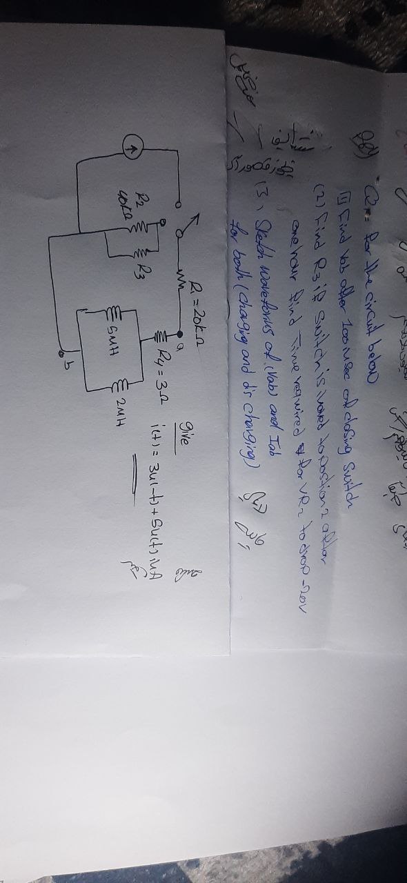
"Q for the circuit below
Find Vab after 100 insec of closing switch
(2) Find R3 if switch is loved to postion 2 after
one hour find Time required for VR₂ to drop-201
13. Sketch Waveforius of (Vab) and Iab
for both (Chagig and dis charging)
22
4040
سلم
R₁ = 20k_n
ww
a
Give
24=32
i+)= 3u1-+ Sucts in A
2MH
SMH
Expert Solution
This question has been solved!
Explore an expertly crafted, step-by-step solution for a thorough understanding of key concepts.

Step by stepSolved in 2 steps with 3 images

Knowledge Booster

Similar questions
- solve this question make sure to solve each branch and step by step calculationsarrow_forwardcan you solve this question handwritten step by step solution with explanation how we obtaines the graph this question is not a part of an assignment its a study questionarrow_forwardANSWER ASAP PLSarrow_forward
- Using second approximation for a diode to calculate the load voltage.arrow_forwardThe reverse breakdown voltage of LED is very low. O True O Falsearrow_forwardSTEP 4: make sure the capacitor is fully charged using the PSB set to 3.3V. Then switch the OAB jumper to 5V and hold SW1 closed again until the LED goes outarrow_forward
- #9arrow_forward10. Determine the peak-to-peak ripple and de output voltages in Figure 5. The transformer has a 36 V rms secondary voltage rating, and the line voltage has a frequency of 60 Hz. 120 Vrms 00000 ellee Rectifier B Figure 5. Rsurge www 10 (2 100 μF www R₁ 3.3 ΚΩarrow_forwardDescribe the operation of Figure 325 (B) by adding jumper wire A to the original circuit.arrow_forward
- v Question Completion Status: forward-biased QUESTION 2 For this clipping circuit, what will be the minimum output voltage when diode is conducting? 10002 120VAC ideal 2,5 V 10:1 +19.47 Volts 25 Volt KA6.97 olts ON E97 Volts QUESTION 3 Click Save oand Submit to save and submit. Click Save AllAnswers to save all ansuers. Saarrow_forwardA practical switch is operating at a switching frequency of 100 kHz and a 0.5 duty cycle. The switch is initially on (the first half cycle). The switch has the following parameters: Von = 0.1 V Volt 80 V Ion - 100 A 10.1 A ton = 0 Loft O Ldelay O a) Draw clear voltage and current waveforms for one switching cycle with all values shown (times, voltages, currents, etc.). b) Find the average power loss in one switching cycle.arrow_forward
arrow_back_ios
arrow_forward_ios
Recommended textbooks for you
- Power System Analysis and Design (MindTap Course ...Electrical EngineeringISBN:9781305632134Author:J. Duncan Glover, Thomas Overbye, Mulukutla S. SarmaPublisher:Cengage Learning

 Electricity for Refrigeration, Heating, and Air C...Mechanical EngineeringISBN:9781337399128Author:Russell E. SmithPublisher:Cengage Learning
Power System Analysis and Design (MindTap Course ...
Electrical Engineering
ISBN:9781305632134
Author:J. Duncan Glover, Thomas Overbye, Mulukutla S. Sarma
Publisher:Cengage Learning
Electricity for Refrigeration, Heating, and Air C...
Mechanical Engineering
ISBN:9781337399128
Author:Russell E. Smith
Publisher:Cengage Learning