
Delmar's Standard Textbook Of Electricity
7th Edition
ISBN: 9781337900348
Author: Stephen L. Herman
Publisher: Cengage Learning
expand_more
expand_more
format_list_bulleted
Related questions
Question
not use ai please
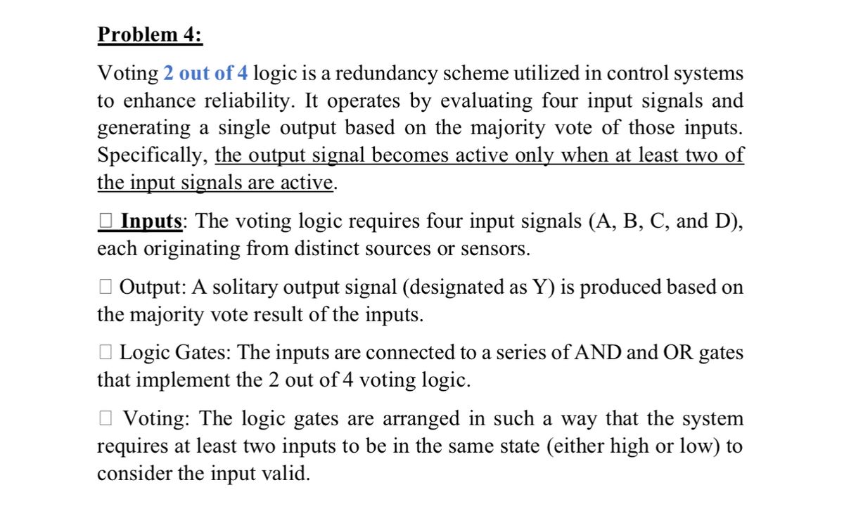

Transcribed Image Text:Problem 4:
Voting 2 out of 4 logic is a redundancy scheme utilized in control systems
to enhance reliability. It operates by evaluating four input signals and
generating a single output based on the majority vote of those inputs.
Specifically, the output signal becomes active only when at least two of
the input signals are active.
Inputs: The voting logic requires four input signals (A, B, C, and D),
each originating from distinct sources or sensors.
☐ Output: A solitary output signal (designated as Y) is produced based on
the majority vote result of the inputs.
Logic Gates: The inputs are connected to a series of AND and OR gates
that implement the 2 out of 4 voting logic.
Voting: The logic gates are arranged in such a way that the system
requires at least two inputs to be in the same state (either high or low) to
consider the input valid.
Expert Solution
This question has been solved!
Explore an expertly crafted, step-by-step solution for a thorough understanding of key concepts.

Step by stepSolved in 2 steps with 3 images

Knowledge Booster

Similar questions
- 2-A) What's the name of the opamp circuit below? Briefly explain the logic. 2-B) Why is there a DC 1 volt offset in Vs sine signal?arrow_forwardDesign a circuit that controls the passage of a signal "A" with the specifications: 1. Output X will equal A when control B and C are the same 2. X will remain HIGH when B and C are different. Hint: Set "A" input as a CLK pin.arrow_forwardQuestion 4) which data shift register does each of the following illustration represent?arrow_forward
- Task 1: You are to design a 4-bit arithmetic unit that consists of a 4-bit adder/subtractor circuit. The arithmetic unit takes as inputs two 4-bit numbers (A and B) and one control input (M) add/subtract selector that selects the type of operation the unit will perform. When the input control is ‘0’, the input numbers are added. When it is set to ‘1’, the two input numbers are subtracted (A - B)arrow_forwardPlease help me to do thisarrow_forwardChoose the true H-bridge motor statements in the list below. O The L298N has a PWM input signal that can be used to control the motor direction. (false, it controls the speed of the motor. O You should always transition through the "Off" state when changing direction with the H-bridge. O The H-bridge provides a means of controlling a motors spin direction. O If all four H-bridge switches are open, the motors will spin. O The H-bridge uses four switches to control the current flow.arrow_forward
- Procedure: You are to design a 4-bit arithmetic unit that consists of a 4-bit adder/subtractor circuit. The arithmetic unit takes as inputs two 4-bit numbers (A and B) and one control input (M) add/subtract selector that selects the type of operation the unit will perform. When the input control is ‘0’, the input numbers are added. When it is set to ‘1’, the two input numbers are subtracted (A - B). Question: Two 4-bit Adder/Subtractor Circuit: Design and construct a 4-bit adder/subtractor circuit. Draw the produced circuit.arrow_forwardWhat is the result of the following FAL instruction? Input L1 Loo a. O b. O C. A HE e. Ladder logic program FAL FILE ARITH/LOGICAL Control Length Position Mode Destination Expression None of the choices (EN) (DN) Incremental (ER) #N7:101 R6:2 6 0 0 N7:100 On successive transitions, data will be copied from N7:100 into the next position in the file #N7:101 until N7:106 is reached Once input A becomes true, data will be copied #N7:101 into the next address of N7:100 O d. On successive transitions, data will be copied #N7:101 into the next address of N7:100 Once input A becomes true, data will be copied six times from #N7:100 into the word #N7:101arrow_forwardPlease help me fill in the worksheet. And for the second part of the worksheet you have to make that circuit on TinkerCAD, with leds, etc.arrow_forward
- Suppose you have three push buttons connected to (B5, B6 & B7) and eight LED's connected to (Do D7): Write a program to flash ON the odd LED's if we press the switch B7 for 0.4s, flash ON the even LED's if we press the switch (B6 for 0.4s and flash ON all the LED's if we press the switch B5 for 0.7s.arrow_forwardThe logic function implemented by the multiplexer circuit is (ground implies a logic "0") 4x1 MUX 1。 1₁ 1₂ 13 S₁ S₂ P Q Y -Farrow_forward(a) Construct a transition table and state graph for the circuit shown in Figure 5. Is the circuit a Mealy or Moore circuit? Does the circuit have any unused states? (b) Assume 00 is the initial state. Draw a timing diagram for the input sequence X = 00110. (c) What is the output sequence for the input sequence? X J1 Q1 CLK K1 J2 Q2 K2 Q2 Figure 5arrow_forward
arrow_back_ios
SEE MORE QUESTIONS
arrow_forward_ios
Recommended textbooks for you
- Delmar's Standard Textbook Of ElectricityElectrical EngineeringISBN:9781337900348Author:Stephen L. HermanPublisher:Cengage Learning
Delmar's Standard Textbook Of Electricity
Electrical Engineering
ISBN:9781337900348
Author:Stephen L. Herman
Publisher:Cengage Learning