
Elements Of Electromagnetics
7th Edition
ISBN: 9780190698614
Author: Sadiku, Matthew N. O.
Publisher: Oxford University Press
expand_more
expand_more
format_list_bulleted
Related questions
Question
How would you draw the kinematic diagram or free body diagram of this problem?

Transcribed Image Text:I Review
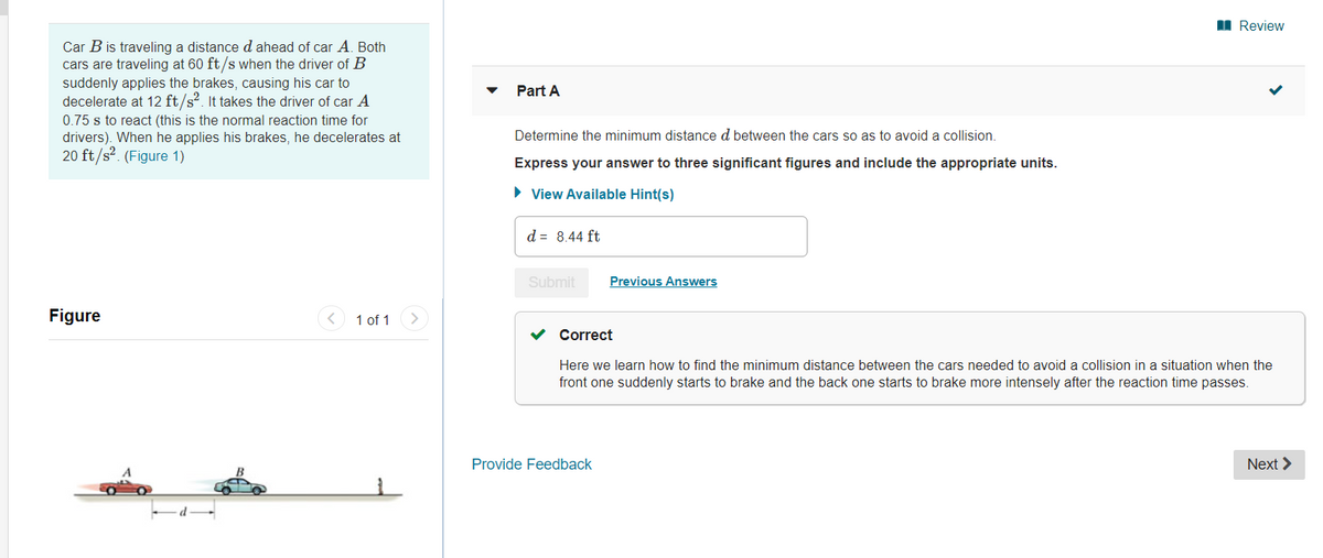
Car B is traveling a distance d ahead of car A, Both
cars are traveling at 60 ft/s when the driver of B
suddenly applies the brakes, causing his car to
decelerate at 12 ft/s?. It takes the driver of car A
Part A
0.75 s to react (this is the normal reaction time for
drivers). When he applies his brakes, he decelerates at
20 ft/s?. (Figure 1)
Determine the minimum distance d between the cars so as to avoid a collision.
Express your answer to three significant figures and include the appropriate units.
• View Available Hint(s)
d = 8.44 ft
Submit
Previous Answers
Figure
1 of 1>
Correct
Here we learn how to find the minimum distance between the cars needed to avoid a collision in a situation when the
front one suddenly starts to brake and the back one starts to brake more intensely after the reaction time passes.
Provide Feedback
Next >
Expert Solution
This question has been solved!
Explore an expertly crafted, step-by-step solution for a thorough understanding of key concepts.

This is a popular solution

Trending nowThis is a popular solution!

Step by stepSolved in 3 steps with 3 images

Knowledge Booster


Learn more about
Need a deep-dive on the concept behind this application? Look no further. Learn more about this topic, mechanical-engineering and related others by exploring similar questions and additional content below.Similar questions
- Motor WORM Cears 2 Fact 4 6 7 (Figure 1) D gear 3, 4, 5, 6, 7 are Spor Gear 1) Draw Free body diagram for (figune 1). draw FBD for gear 2, 3, 4, 5, 6, 7. Should include Force [Fr, Ft), Torque (T] (and speed roration (n) [quess or make Ass Compling] ASS 2) Estimate the torque required to spin (Just the equation No calculation (Example: T = F₂₂ cos(p) ₂)arrow_forwardNow consider the figure shown below. N CG -A tip In the above figure the block is just on the verge of tipping: W and N act through point A and thus exert zero torque about point A. The incline angle, Otip, is the incline angle beyond which the block will tip, since increasing the angle beyond Otip will move the CG beyond where there is a point of support below it, as in the previous figure. It is not difficult to show, using some geometry and trigonometry, that Otip is given by Orip = tan' (w / h) (1) Equation (1) agrees with our intuition: If the block is short and wide (h small, w large) the block will be more difficult to tip (Otip is large) and if the block is tall and narrow (h large, w small) the block will be easier to tip (0tip is small). It is now not difficult to see why the automotive industry defines a safety factor describing how easily a vehicle will rollover as (roughly) vehicle width / vehicle height. The larger this safety factor is, the more resistant the vehicle is…arrow_forwardMotor WORM (ears 2 Fact 4 6 7 (Figure 1) D gear 3, 4, 5, 6, 7 are Spor Gear 1) Draw Free body diagram for (figune 1), draw FBD for gear 2, 3, 4, 5, 6, 7. Should include Force [Fr, Ft), Torque (T] (and speed roration (n) [quess or make ASS compling] 2) Estimate the torque required to spin (Just the equation No calculation ( Example: T = F₁₂ cos(p) ₂)arrow_forward
- Hi, I have been given this pin-jointed frame analysis to solve (see pictures of the structure attached). Can you help me answer all the questions below? Especially the one about the bending moment and shear force. The Figure 2 attached is a simplified structure to undertake a structural analysis on a concept design for a low cost stroller/buggy for children. The buggy consists of a number of metal sections that are pin-jointed together. The buggy is designed to accommodate a child of mass no more than 20 kg, sat on the seat which is supported at four points (Fc) on the frame of the buggy. Assume that the weight of the child is equally distributed across all of the points indicated on Figure 2 as Fc. Assume that there are no additional forces applied to the handle of the buggy, that the buggy is static (stationary) and that the buggy, and the elements of the frame have no mass. At points A and G, there are roll supports. At Points B, F and D there are the pin supports. I am required…arrow_forwardFor the mechanism pictured below: perform displacement analysis both graphically and analytically (A3)arrow_forwardNon-Uniform/local Scaling: Want to scale our cube by different values for each direction? a 0 0 0 e 00 ojo Use Ts*= = 0 0 00 Where a scales the x coordinate, e scales the y coordinate, and j scales the z coordinate. 8. Show that for a = 1/2, e = 1/3, and j = 1 scales our cube down to the unit cube by multi- 0 0 TO 2 2 0 0 2 201 [1/2 0 0 1/3 0 0 300 3 3 0 0 3 1 0 10 1 1 0 0 1 1 1 1 1 plying T, *.M 0 1 0000 1 1 1 1arrow_forward
arrow_back_ios
arrow_forward_ios
Recommended textbooks for you
- Elements Of ElectromagneticsMechanical EngineeringISBN:9780190698614Author:Sadiku, Matthew N. O.Publisher:Oxford University Press
 Mechanics of Materials (10th Edition)Mechanical EngineeringISBN:9780134319650Author:Russell C. HibbelerPublisher:PEARSON
 Thermodynamics: An Engineering ApproachMechanical EngineeringISBN:9781259822674Author:Yunus A. Cengel Dr., Michael A. BolesPublisher:McGraw-Hill Education
  Control Systems EngineeringMechanical EngineeringISBN:9781118170519Author:Norman S. NisePublisher:WILEY
 Mechanics of Materials (MindTap Course List)Mechanical EngineeringISBN:9781337093347Author:Barry J. Goodno, James M. GerePublisher:Cengage Learning
 Engineering Mechanics: StaticsMechanical EngineeringISBN:9781118807330Author:James L. Meriam, L. G. Kraige, J. N. BoltonPublisher:WILEY
Elements Of Electromagnetics
Mechanical Engineering
ISBN:9780190698614
Author:Sadiku, Matthew N. O.
Publisher:Oxford University Press
Mechanics of Materials (10th Edition)
Mechanical Engineering
ISBN:9780134319650
Author:Russell C. Hibbeler
Publisher:PEARSON
Thermodynamics: An Engineering Approach
Mechanical Engineering
ISBN:9781259822674
Author:Yunus A. Cengel Dr., Michael A. Boles
Publisher:McGraw-Hill Education
Control Systems Engineering
Mechanical Engineering
ISBN:9781118170519
Author:Norman S. Nise
Publisher:WILEY
Mechanics of Materials (MindTap Course List)
Mechanical Engineering
ISBN:9781337093347
Author:Barry J. Goodno, James M. Gere
Publisher:Cengage Learning
Engineering Mechanics: Statics
Mechanical Engineering
ISBN:9781118807330
Author:James L. Meriam, L. G. Kraige, J. N. Bolton
Publisher:WILEY