
Mechanics of Materials (MindTap Course List)
9th Edition
ISBN: 9781337093347
Author: Barry J. Goodno, James M. Gere
Publisher: Cengage Learning
expand_more
expand_more
format_list_bulleted
Related questions
Question
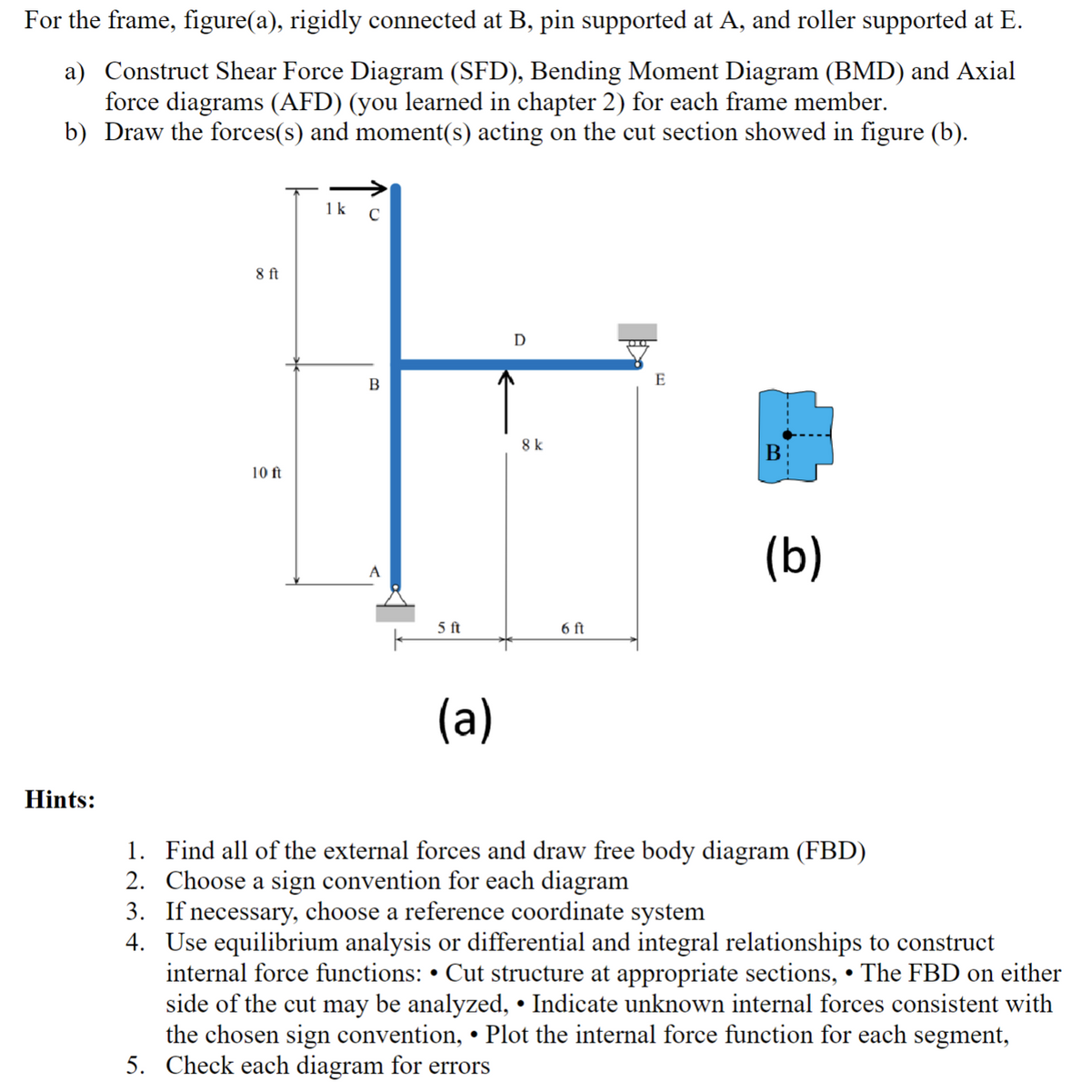

Transcribed Image Text:For the frame, figure(a), rigidly connected at B, pin supported at A, and roller supported at E.
a) Construct Shear Force Diagram (SFD), Bending Moment Diagram (BMD) and Axial
force diagrams (AFD) (you learned in chapter 2) for each frame member.
b) Draw the forces(s) and moment(s) acting on the cut section showed in figure (b).
8 ft
10 ft
1 k
с
B
A
5 ft
(a)
D
8 k
6 ft
E
B
(b)
Hints:
1. Find all of the external forces and draw free body diagram (FBD)
2. Choose a sign convention for each diagram
3. If necessary, choose a reference coordinate system
4. Use equilibrium analysis or differential and integral relationships to construct
internal force functions: • Cut structure at appropriate sections, •The FBD on either
side of the cut may be analyzed, • Indicate unknown internal forces consistent with
the chosen sign convention, • Plot the internal force function for each segment,
5. Check each diagram for errors
Expert Solution
This question has been solved!
Explore an expertly crafted, step-by-step solution for a thorough understanding of key concepts.

Step by stepSolved in 2 steps with 1 images

Knowledge Booster

Similar questions
- Frame ABC has a moment release just left of joint B. Find axial force N, shear force V, and moment M at the top of column AB. Write variables N, V, and M in terms of variables P and L.arrow_forwardA seesaw weighing 3 lb/ft of length is occupied by two children, each weighing 90 lb (see figure). The center of gravity of each child is 8 ft from the fulcrum. The board is 19 ft long, 8 in. wide, and 1.5 in. thick. What is the maximum bending stress in the board?arrow_forwardRepeat 1.3-9 but use the method of sections go find member forces in AC and BD.arrow_forward
- I need detailed solution in Handwritten format with diagram. Please don't use chatgpt.arrow_forwardPlease break down every step so I can understand the complete concept of how to algebraically work this out. Thank you.arrow_forwardFor the frame system shown in the figure below, a) Calculate the support reactions. b) Calculate the shear force (V) and bending moment (M) functions using THE METHOD OF SECTIONS. c) Draw the diagrams of those shear force (V) and bending moment (M) functions. Notes: There is a pin support at point A. There is a roller support at point C. (AB - BC) P=8 B w = P kN/m 2 m Carrow_forward
- Draw the Shear force diagram & Bending moment diagram for the cantilever beam as shown in figure, mark the salient points in the diagram. Neglect the self-weight of the beam, where F1 =10 N, F2 =60N, F3 =30 N, F4 =1ON, a =5 m, b=2 m, c=3 m, d=5 m F4 F3 F2 F1 E A d. aarrow_forwardA 16 kN/m 80 kN.m C 75 kN B 2 m 2m 1 m 2 m 5 m El is constant all across the structure. D Use the Force Method to analyse the beam shown in the Figure by introducing hinges and corresponding redundant bending moments at points A, B, C. Plot the bending moment (M) and shear force (V) diagrams for the loading shown. A) Find X1 (see the similar example(s) of the note if you do not know what X1, X2 and X3 are) - XI is associated with the unit moment at A. B) Find X2. Note: X2 is associated with the unit moment at B. C) Find X3. Note: X3 is associated with the unit moment at C. D) Based on X1, X2, and X3: Find Ray (Vertical reaction at A). E) Based on X1, X2, and X3: Find Roy (Vertical reaction at D)arrow_forwardDon't use Artificial intelligencearrow_forward
- Given l= 1000 mm and P= 4000 N, draw internal shear force and moment diagram.arrow_forwardusing MATLABarrow_forwardThe engine on the lift weighs 900 N. There are pins at points A, B, C, D, E, and G. Note, the pin at D is for the roller only as the attachment between CBD and ED is a weld. a) Determine the internal normal force, shear force and bending moment at points F and H. b) Draw the normal, shear, and bending moment diagrams for the element GAC and element CBD. c) Determine the maximum normal force, shear force and bending moment in this structure. 10° 1250 mm 500 mm | 350 mm F A C 850 mm AREAA 550 mm Н D 700 mm 1500 mmarrow_forward
arrow_back_ios
SEE MORE QUESTIONS
arrow_forward_ios
Recommended textbooks for you
- Mechanics of Materials (MindTap Course List)Mechanical EngineeringISBN:9781337093347Author:Barry J. Goodno, James M. GerePublisher:Cengage Learning
Mechanics of Materials (MindTap Course List)
Mechanical Engineering
ISBN:9781337093347
Author:Barry J. Goodno, James M. Gere
Publisher:Cengage Learning