
Mechanics of Materials (MindTap Course List)
9th Edition
ISBN: 9781337093347
Author: Barry J. Goodno, James M. Gere
Publisher: Cengage Learning
expand_more
expand_more
format_list_bulleted
Related questions
Question
thumb_up100%
Don't use Artificial intelligence

Transcribed Image Text:2:43 AM P G
+599 39
Expert Help
EaEDnD#9140
02:43
Problem 5-5
Determine the values and draw the diagrams for
shear force and bending moment due to the imposed
load on overhanging beam shown in figure 5-5(a)
and find the position of point of contra-flexure, if any.
1 kN
5 kN/m
4 KN
2 kN
70
40
70
40.40
60
Civilengineeronline.com
A
B
C
D
E
F
G
All distances in cm
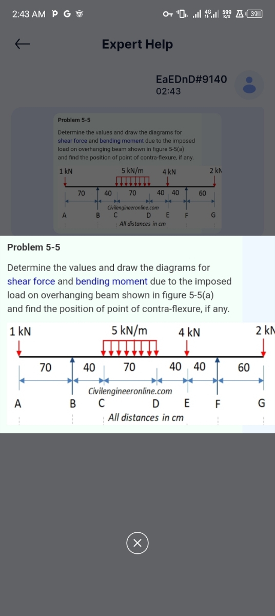
Problem 5-5
Determine the values and draw the diagrams for
shear force and bending moment due to the imposed
load on overhanging beam shown in figure 5-5(a)
and find the position of point of contra-flexure, if any.
1 kN
70
70
5 kN/m
4 KN
40
70
4040
60
60
Civilengineeronline.com
2 kN
A
B
с
DEF
G
All distances in cm
Х
Expert Solution
This question has been solved!
Explore an expertly crafted, step-by-step solution for a thorough understanding of key concepts.

Step by stepSolved in 2 steps with 1 images

Knowledge Booster

Similar questions
- Statics with Applications homework problem. Find the forces in the following members using any method. AC, EA, FD, GFarrow_forward4:48 68 O E B18 Statics_Moment.. o 240 N 2. A prybar is used to remove a nail as 15° shown. Determine 350 mm the moment of the 240 N force about the point o of 65° contact between the prybar and the small support block. 30 mm PROBLEMS 240cos10=236.35 N Mo=? 240 N 15° 65 240sin 10=41.68 N 350 mm M=236.35(0.35) +41.68(0.03)=83.97 N -m 65 (clockwise direction) 30 mm PROBLEMS 900 mm 700 mm 3. An experimental device imparts a force of magnitude F = 225 N to the front edge of the rim at A to simulate the F 300 mm effect of a slam dunk. Determine the moments of the force F about point O and about point B. Finally, locate, 3050 mmarrow_forwardI need detailed solution in Handwritten format with diagram. Please don't use chatgpt.arrow_forward
- pls very urgentarrow_forwardS00 Ib In the fig. shown, compute the ff: (16-18) the resultant using cosine law (force polygon) 60 R = 35 (19-20) the angle of the R measured 500 lb cW from the x- axis.arrow_forwardPlease break down every step so I can understand the complete concept of how to algebraically work this out. Thank you.arrow_forward
- The following diagram corresponds to questions 1 to 3. A beam rests on two sharp edges as shown on the image. The beam has a length of 7,50 m and a mass of 4,25 kg. Object 1 has a mass of 1,50 kg; object 2 has a mass of 2,35 kg. Point P is 0,50 m form the center of the beam. CG 1. How much is the torque done by object 1 around point P? A. 55,2 N*m B. 7,36 N*m C. 62,5 N*m D. Object 1 doesn't exert a torque. 2. How much is the torque done by the force of gravity of the beam around point P? A. 20,8 N*m N-m ך177 .B C. 156 N*m D. 313 N*m 3. If you needed to cancel the nomal forces of the two objects, where you should place object 2? The axis of rotation is point P. A. 3,30 m from point B. 9,18 m from point P C. 5,69 m from point P D. 3,62 m from point Parrow_forward3-25 what i asarrow_forwardPlease:arrow_forward
arrow_back_ios
SEE MORE QUESTIONS
arrow_forward_ios
Recommended textbooks for you
- Mechanics of Materials (MindTap Course List)Mechanical EngineeringISBN:9781337093347Author:Barry J. Goodno, James M. GerePublisher:Cengage Learning
Mechanics of Materials (MindTap Course List)
Mechanical Engineering
ISBN:9781337093347
Author:Barry J. Goodno, James M. Gere
Publisher:Cengage Learning