Introductory Circuit Analysis (13th Edition)
13th Edition
ISBN: 9780133923605
Author: Robert L. Boylestad
Publisher: PEARSON
expand_more
expand_more
format_list_bulleted
Question

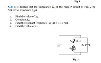
Transcribed Image Text:Fig. 1
Q2: It is desired that the impedance Z of the high-Q circuit of Fig. 2 be
50k<0° at resonance (fp).
2602
d.
a.
b.
Find the value of XL.
Compute Xc.
C. Find the resonant frequency (fp) if L = 16 mH.
Find the value of C.
ZT
R₁ 50 N
Xc
Χ
Fig. 2
Expert Solution
This question has been solved!
Explore an expertly crafted, step-by-step solution for a thorough understanding of key concepts.
Step by stepSolved in 2 steps with 2 images

Knowledge Booster
Similar questions
- 000 Q4/ It is desired that the impedance ZT of the high Q circuit in Fig. 4 be 50 k [0 at resonance (fp). Answer only three of the following:- a. Find the value of XL. b. Compute XC. c. Find the resonant frequency (fp) if L = 16 mH. d. Find the value of C R₁50 n 14 Marks xxx Bu fr ZT XLarrow_forward2. For the circuit of figure P.2 with AC input find: c. (10) the impedance seen by the source. d. (10) the resonant frequency as a function of w, R, C1, C2 and L. e. (10) Plot the behavior of the voltage at R as a function of frequency. C2 ww R нн Vin(t) 01 L Figure P.2arrow_forward6arrow_forward
- For the network of Figure below with ßhe-125, re-11 2, Che 20PF, Cbc-2.4PF, Cce-0.5PF, neglect wiring in and out capacitors. (5 marks) a. Find 4mid = Vo/Vi. b. Determine the lower cutoff frequency fi c. Determine the higher cutoff frequency fH. +10 V Rc 22 KSP 2.2K G 10 µF R W 600 9 10μF RE 470 92 10Farrow_forwardDetermine the gain, Vout/ Vin, for the given circuit. What is the resonant frequency of the circuit, in Hertz? + Vout Vinarrow_forwardQ.4: Choose the suitable choice for the following sentences. 1. At any resonant circuit the input impedance is ....... a. XL. b. RT. c. XC. 2. The locus of inductive load is a vector in the …... quadrant. a. 4th. b. 2nd. c. 3rd. 3. For non-sinusoidal input signal, the power dissipated in a resistance is equal to ............ a. 2I2R. b. Iav2R. c. Ieff2R. 4. Applying Kirchhoff's laws to RL & RC transient circuits produces Equations of type:a. Time-Depend. b. Time-Variable. c. Differential. 5. The Differential Equations applied RL & RC transient circuits are:a. Third-order b. Second-order c. First-order 6. Electrical energy is stored in ........ a. Inductance. b. Capacitance. c. Both-of-them. 7. .......... is obtained in parallel resonance circuit. a. Vmax. b. Imax. c. Pmax. 8. The total impedance angle is ............ on the frequency of the harmonic.a. Dependent. b. Independent. c. Both-of-them. 9. In transient circuit, the capacitor behaves as ................ when the switch…arrow_forward
- Complete Part A, Thank you! I will give a great rating!arrow_forwardEx. 1340. Refer to Figure setH(1340). Given: w1=1 rad/sec and G(s) = 34/s. Determine asymptotic (also actual): G1,G2,Ph1, mc where gains are in dB, frequencies are in rad/sec, and phases are in degrees. mc=Bode Plot type code. ans:4arrow_forwardQ3: A series circuit has a resonant frequency of 10 kHz. The resistance of the circuit is 52, and Xc at resonance is 200 2. a. Find the bandwidth b. Find the cutoff frequencies. c. Find Qs. d. If the input voltage is 30V<0°, find the voltage across the coil and capacitor in phasor form. e. Find the power dissipated at resonance.arrow_forward
- H.W: A resistor of resistance R=1000 2is maintained at 17 °C and it shunted by 100 uH inductor. Determine the ms noise voltage across the inductor over a frequency bandwi dth of: Ans: 182 x10° volt Ans: 9.22 x10 volt Ans: 2.34 x10 volt i) 15.9 kHz ii) i) 159 kHz 1590 kHzarrow_forward4. The Bode plot shown below represents the voltage gain of a particular amplifier. Sketch the input and output waveforms, v,() and v(1) if the input to the amplifier is v, (1) = 10 + 10cos(400t + 60°) mV. Use the graph paper on the next page for your sketches and label the minimum and maximum value for each waveform. 60 Bode Diagram 58 56 54 52 50 48 46 44 42 40 -5 -10 -15 -20 -25 -30 -35 -40 -45 -50 -55 -60 100 101 102 Frequency (rad/s) 10 104 105 (Bap) aseud Magnitude (dB)arrow_forwardIf vsig is a triangle waveform, determine the maximum amplitude that vsig can have? Showyour calculation.arrow_forward
arrow_back_ios
SEE MORE QUESTIONS
arrow_forward_ios
Recommended textbooks for you
 Introductory Circuit Analysis (13th Edition)Electrical EngineeringISBN:9780133923605Author:Robert L. BoylestadPublisher:PEARSON
 Delmar's Standard Textbook Of ElectricityElectrical EngineeringISBN:9781337900348Author:Stephen L. HermanPublisher:Cengage Learning
 Programmable Logic ControllersElectrical EngineeringISBN:9780073373843Author:Frank D. PetruzellaPublisher:McGraw-Hill Education
 Fundamentals of Electric CircuitsElectrical EngineeringISBN:9780078028229Author:Charles K Alexander, Matthew SadikuPublisher:McGraw-Hill Education
 Electric Circuits. (11th Edition)Electrical EngineeringISBN:9780134746968Author:James W. Nilsson, Susan RiedelPublisher:PEARSON
 Engineering ElectromagneticsElectrical EngineeringISBN:9780078028151Author:Hayt, William H. (william Hart), Jr, BUCK, John A.Publisher:Mcgraw-hill Education,

Introductory Circuit Analysis (13th Edition)
Electrical Engineering
ISBN:9780133923605
Author:Robert L. Boylestad
Publisher:PEARSON

Delmar's Standard Textbook Of Electricity
Electrical Engineering
ISBN:9781337900348
Author:Stephen L. Herman
Publisher:Cengage Learning

Programmable Logic Controllers
Electrical Engineering
ISBN:9780073373843
Author:Frank D. Petruzella
Publisher:McGraw-Hill Education

Fundamentals of Electric Circuits
Electrical Engineering
ISBN:9780078028229
Author:Charles K Alexander, Matthew Sadiku
Publisher:McGraw-Hill Education

Electric Circuits. (11th Edition)
Electrical Engineering
ISBN:9780134746968
Author:James W. Nilsson, Susan Riedel
Publisher:PEARSON

Engineering Electromagnetics
Electrical Engineering
ISBN:9780078028151
Author:Hayt, William H. (william Hart), Jr, BUCK, John A.
Publisher:Mcgraw-hill Education,