
Introductory Circuit Analysis (13th Edition)
13th Edition
ISBN: 9780133923605
Author: Robert L. Boylestad
Publisher: PEARSON
expand_more
expand_more
format_list_bulleted
Related questions
Question
PEN PAPER SOLUTION REQUIRED BUT NOT USING CHAT GPT PLEASE
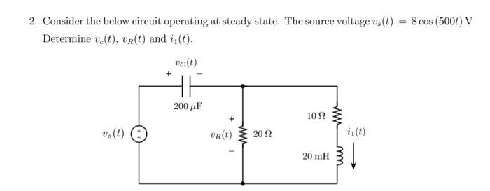

Transcribed Image Text:2. Consider the below circuit operating at steady state. The source voltage v,(t) = 8 cos (500t) V
Determine v(t), vR(t) and i₁(t).
+
vc(t)
v(t)
200 μF
10 Ω
VR(t)
20 Ω
is(t)
20 mH
m
SAVE
AI-Generated Solution
info
AI-generated content may present inaccurate or offensive content that does not represent bartleby’s views.
Unlock instant AI solutions
Tap the button
to generate a solution
to generate a solution
Click the button to generate
a solution
a solution
Knowledge Booster

Similar questions
- 2. Find the steady-state current iz(t) and vz(t) in the following circuit, where is(t) = 5 sin(100t + 40°) A. L1 100 mH ix is(t) sine C1 1 mF R1 20 Ω. Vxarrow_forwardPlease all subpart is compulsory ASAParrow_forwardFind the steady-state expression for vo(t) in the following circuit if vg (t) = 64 cos(8000t) V. 31.25 nF HE + Vg + - 2 ΚΩ Vo 500 mHarrow_forward
- a. For the circuit shown below: 20 2 1 mH ll R Vs (*) 100cos(2001) V 25 mF the following LTspice netlist can be used to determine the magnitude and phase angle of the steady-state ĀC part of v: Vs 3 2 AC 100 0 R 3 0 20 L0 1 1m C 1 2 25m .AC DEC 1 31.83098861 31.83098861 Run the simulation and identify the desired results in the output file. b. Use the phasor analysis method to determine the analytical solution, and verify that the LTspice result is correct.arrow_forwardFind the steady-state is (a) w = 400rad/s, 100 cos (wt) mA 375 mH 12 cos (400 t) V 100 S2 ww vo(t) + voltage of circuit when the frequency of the current source (b) w = 200rad/sarrow_forwardThe input to the circuit shown in the following figure is the voltage of the voltage source vs (t) = 5 cos(2t + 45°) V. The output is the inductor voltage v(t). Determine steady-state output voltage. U₂ (1) 0.1 F HH 492 www + 3 H v(1)arrow_forward
- 2.-For the circuit below, use nodal analysis to calculate the steady-state expression for v(t) if v(t) = 2cos(10′t) V.ε 100 ΚΩ Ug 5 ΚΩ m Va 20 ΚΩ 100 pF 10 pF HE 5V –5V 8° 40 ΚΩarrow_forwardThe AC circuit below is in steady state. (a) What is the maximum value of the waveform ia(t)? (b) Find the complex power S supplied by the voltage source v₁. (c) Find the average power P received by that same voltage source v₁. v₁ (t) = A₁ cos(10t + B₁) is R C is A₁ R > Ja (d) In the circuit below, the waveform is (t) is periodic with period T. The resistor R is the same as in the circuit above. Find the value of K such that the average power received by the resistor in the circuit below is the same as by the resistor in the circuit above. T K k. ia L2 R: C: L: k: A1: B1: T: 202 100 mF 100 mH 3 A/A 10 V -15 degrees 4 sarrow_forwardI VY O non-sinusoidal... -> For the circuit shown below calculate the output voltage Vo(t). v(t)=cos(t)+2cos (2t)arrow_forward
- A voltage is given by v( t )=10 sin(1000πt+30°). First, use a cosine function to express v(t). Then, find the angular frequency, the frequency in hertz, the phase angle, the period, and the rms value. Find the power that this voltage delivers to a 50-Ω resistance. Find the first value of time after t=0 that v(t) reaches its peak value. Sketch v(t) to scale versus time. * Denotes that answers are contained in the Student Solutions files. See See Appendix E for more information about accessing the Student Solutions.arrow_forward3arrow_forward2) A current source in a linear circuit has i(t) = 15 cos(25nt + 25º) A. a) What is the amplitude of the current? b) What is the angular frequency? c) Find the frequency of the current d) Calculate i, at t= 2 msarrow_forward
arrow_back_ios
SEE MORE QUESTIONS
arrow_forward_ios
Recommended textbooks for you
- Introductory Circuit Analysis (13th Edition)Electrical EngineeringISBN:9780133923605Author:Robert L. BoylestadPublisher:PEARSON
 Delmar's Standard Textbook Of ElectricityElectrical EngineeringISBN:9781337900348Author:Stephen L. HermanPublisher:Cengage Learning
 Programmable Logic ControllersElectrical EngineeringISBN:9780073373843Author:Frank D. PetruzellaPublisher:McGraw-Hill Education
  Fundamentals of Electric CircuitsElectrical EngineeringISBN:9780078028229Author:Charles K Alexander, Matthew SadikuPublisher:McGraw-Hill Education
 Electric Circuits. (11th Edition)Electrical EngineeringISBN:9780134746968Author:James W. Nilsson, Susan RiedelPublisher:PEARSON
 Engineering ElectromagneticsElectrical EngineeringISBN:9780078028151Author:Hayt, William H. (william Hart), Jr, BUCK, John A.Publisher:Mcgraw-hill Education,
Introductory Circuit Analysis (13th Edition)
Electrical Engineering
ISBN:9780133923605
Author:Robert L. Boylestad
Publisher:PEARSON
Delmar's Standard Textbook Of Electricity
Electrical Engineering
ISBN:9781337900348
Author:Stephen L. Herman
Publisher:Cengage Learning
Programmable Logic Controllers
Electrical Engineering
ISBN:9780073373843
Author:Frank D. Petruzella
Publisher:McGraw-Hill Education
Fundamentals of Electric Circuits
Electrical Engineering
ISBN:9780078028229
Author:Charles K Alexander, Matthew Sadiku
Publisher:McGraw-Hill Education
Electric Circuits. (11th Edition)
Electrical Engineering
ISBN:9780134746968
Author:James W. Nilsson, Susan Riedel
Publisher:PEARSON
Engineering Electromagnetics
Electrical Engineering
ISBN:9780078028151
Author:Hayt, William H. (william Hart), Jr, BUCK, John A.
Publisher:Mcgraw-hill Education,