Introductory Circuit Analysis (13th Edition)
13th Edition
ISBN: 9780133923605
Author: Robert L. Boylestad
Publisher: PEARSON
expand_more
expand_more
format_list_bulleted
Question

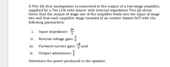
Transcribed Image Text:A Five (5) ohm loudspeaker is connected to the output of a two-stage amplifier,
supplied by a Ten (10) volts source with internal impedance Two (2) ohms.
Given that the output of stage one of the amplifier feeds into the input of stage
two and that each amplifier stage consists of an emitter biased BJT with the
following parameters:
i. Input impedance:
34
ii. Reverse voltage gain:
-8
Forward current gain: and
iv. Output admittance:
Determine the power produced in the speaker.
Expert Solution
This question has been solved!
Explore an expertly crafted, step-by-step solution for a thorough understanding of key concepts.
Step by stepSolved in 2 steps with 2 images

Knowledge Booster
Similar questions
- QUESTION 1 Design a high efficiency 3.3 V, 5A d.c.to d.c. power converter from a 4 to 5.5 Vdc source. The maximum allowable inductor current ripple and output voltage ripple are 0.1A and 20 mV, respectively. Assume a switching frequency of 20 kHz. a) Design a suitable converter power circuit using a MOSFET switch, showing all calculation of inductor and capacitor values and drawing a circuit diagram of the final design including component values. Indicate the peak inverse voltage and forward current rating of any diode required, and the maximum drain- source voltage of the MOSFET. b) On the Schematic diagram, draw the path of the current flow during the ON time and the OFF time. c) Describe the effect of changing the values of the inductor and the capacitor in the circuit. d) What is the effect of switching frequency in the circuit? e) Draw the schematic diagram of a circuit with the output voltage higher than the input voltage.arrow_forward3) Explain the construction, principle of operation, circuit and applications of Variable reluctance transducer with neat diagrams. 4) Describe the construction of LVDT and explain its principle of operation with the aid of diagram, list the advantages, disadvantages and applications of LVDT.arrow_forward1. The DC-DC converter has several circuit configurations. a) (Draw a simple connection of IGBT switch, diode and inductor that can discriminate between Buck, Boost and Buck-Boost converter circuits respectively.) b) ('A Boost converter produces an output voltage, Vo that is more than or equal to the input voltage, Vi. Based on this statement develop the equation for the relationship between Vo Viand D. where D represents the duty ratio. You can use any suitable diagram to illustrate your answer.)arrow_forward
- R2 R, 1+ -VEE =- 15 V V. out in R, R1 R1 = 5.6 kQ V out Vin Vcc =+ 15 V Rin 19) calculate the value of R2 required for a closed-loop voltage gain of 5V/Varrow_forward5, a) Determine Vdsat when ID=.5 mA. b) Determine Kn when ID = 0.5 Amps. (Show your work!) c) Determine VTN. (Show your work!) d) Vgs Consider the circuit and corresponding graph, shown below. ID (mA) 0.60 0.50 0.40 0.30 0.20 0.10 0.00 0 0.5 Vds 1 1.5 2 2.5 Vds 3 3.5 4 4.5 5 -Vgs = 1V - Vgs = 1.1V - Vgs = 1.2V - Vgs = 1.3Varrow_forwardFind the following: DC gain, inductor current ripple and output voltage ripple: For DC-DC Buck converter: 1-Draw all circuits in all position 2-Sketch the transistor current waveform 3-Derive analytical expressions for the dc components of the capacitor voltages and inductor currents. 4-Derive analytical expressions for the peak ripple magnitudes of the input filter inductor current and capacitor voltage.arrow_forward
- ........ (Figure-1) R. RB= 380kN,Rc= 1kN B = 100, VBB = Vcc=12V RB ww Vec CC ......... I, V CE СЕ V ВЕ BB Q-1-b) Describe briefly the input / output characteristics and application of Common Emitter BJT Configurationarrow_forwardHi! I need answer for questions below: Principles of operation of darlington pair DC analysis of darlington pair equation/formulas. (Applying KVL, current gain, voltage gaing etc.) AC analysis of darlington pair equation/formulas. (Applying KVL, current gain, voltage gaing etc.)arrow_forward1arrow_forward
- circuits by using the small signal models of the transistor. Assume the Early voltage of the transistors are infinitely large. Calculate the small-signal input and output impedances of the following Vcc R1 R1 Rout VB RE Rin R2arrow_forwardQ9. Draw Zener regulator circuit to obtain regulated DC voltage 6.8 V. Considering input DC voltage in the range from 10V to 30V. Consider load resistance of 110KQ. Q10. Determine maximum and minimum value of Zener current if value of series resistance is 1 K, load resistance is 2KN and input varies from 10V to 30V. Zener voltage is 5 V. Q11. What is LED?arrow_forward4) Consider the clamping circuit below, assume Vref=3 V and Vin=5sin(wt) ..Draw the output voltage waveform. Clearly mark the max and min of the voltage.. Vrefarrow_forward
arrow_back_ios
SEE MORE QUESTIONS
arrow_forward_ios
Recommended textbooks for you
 Introductory Circuit Analysis (13th Edition)Electrical EngineeringISBN:9780133923605Author:Robert L. BoylestadPublisher:PEARSON
 Delmar's Standard Textbook Of ElectricityElectrical EngineeringISBN:9781337900348Author:Stephen L. HermanPublisher:Cengage Learning
 Programmable Logic ControllersElectrical EngineeringISBN:9780073373843Author:Frank D. PetruzellaPublisher:McGraw-Hill Education
 Fundamentals of Electric CircuitsElectrical EngineeringISBN:9780078028229Author:Charles K Alexander, Matthew SadikuPublisher:McGraw-Hill Education
 Electric Circuits. (11th Edition)Electrical EngineeringISBN:9780134746968Author:James W. Nilsson, Susan RiedelPublisher:PEARSON
 Engineering ElectromagneticsElectrical EngineeringISBN:9780078028151Author:Hayt, William H. (william Hart), Jr, BUCK, John A.Publisher:Mcgraw-hill Education,

Introductory Circuit Analysis (13th Edition)
Electrical Engineering
ISBN:9780133923605
Author:Robert L. Boylestad
Publisher:PEARSON

Delmar's Standard Textbook Of Electricity
Electrical Engineering
ISBN:9781337900348
Author:Stephen L. Herman
Publisher:Cengage Learning

Programmable Logic Controllers
Electrical Engineering
ISBN:9780073373843
Author:Frank D. Petruzella
Publisher:McGraw-Hill Education

Fundamentals of Electric Circuits
Electrical Engineering
ISBN:9780078028229
Author:Charles K Alexander, Matthew Sadiku
Publisher:McGraw-Hill Education

Electric Circuits. (11th Edition)
Electrical Engineering
ISBN:9780134746968
Author:James W. Nilsson, Susan Riedel
Publisher:PEARSON

Engineering Electromagnetics
Electrical Engineering
ISBN:9780078028151
Author:Hayt, William H. (william Hart), Jr, BUCK, John A.
Publisher:Mcgraw-hill Education,