
Principles of Foundation Engineering (MindTap Course List)
9th Edition
ISBN: 9781337705028
Author: Braja M. Das, Nagaratnam Sivakugan
Publisher: Cengage Learning
expand_more
expand_more
format_list_bulleted
Related questions
Question
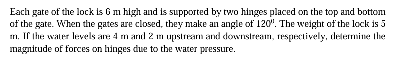

Transcribed Image Text:Each gate of the lock is 6 m high and is supported by two hinges placed on the top and bottom
of the gate. When the gates are closed, they make an angle of 120º. The weight of the lock is 5
m. If the water levels are 4 m and 2 m upstream and downstream, respectively, determine the
magnitude of forces on hinges due to the water pressure.
Expert Solution
This question has been solved!
Explore an expertly crafted, step-by-step solution for a thorough understanding of key concepts.

Step by stepSolved in 2 steps

Knowledge Booster

Similar questions
- 6. Figure 4 shows a segment gate of semicircular cross section which is 10 ft long and 8 ft in diameter. Water stands at a depth of 8 ft on the left-hand side and 4 ft on the right-hand side. Determine both the magnitude and the direction of the total (net) hydrostatic force on the gate. 8.00 t 4.00arrow_forwardFor the data given in this problem, determine the magnitude of the active thrust on the wall retaining a c soil, using the procedure discussed in Section 16.10. Given H = 15.0 ft, c = 100 lb/ft2, = 26, = 115 lb/ft3, kv = 0, and kh = 0.3.arrow_forwardThe cross section of a braced cut supporting a sheet pile installation in a clay soil is shown in Figure 14.22. Given: H = 12 m, clay = 17.9 kN/m3, = 0, c = 75 kN/m2, and the center-to-center spacing of struts in plan view, s = 3 m. a. Using Pecks empirical pressure diagrams, draw the earth-pressure envelope. b. Determine the strut loads at levels A, B, and C.arrow_forward
- Determine the factor of safety against bottom heave for the braced cut described in Problem 15.18. Use Eqs. (15.66) and (15.70). For Eq. (15.70), assume the length of the cut, L = 18 m. 15.18 Refer to Figure 15.51 in which = 17.5 kN/m3, c = 60 kN/m2, and center-to-center spacing of struts is 5 m. Draw the earth pressure envelope and determine the strut loads at levels A, B, and C. FIG. 15.51arrow_forwardA braced cut shown in Figure P19.3 is to be made to a depth of 9.0 m in a saturated clay deposit where the unit weight is 17.65 kN/m3 and the undrained shear strength is 30 kN/m2. The struts are spaced horizontally at 3.0 m center to center. Find the strut loads.arrow_forward
arrow_back_ios
arrow_forward_ios
Recommended textbooks for you
- Principles of Foundation Engineering (MindTap Cou...Civil EngineeringISBN:9781337705028Author:Braja M. Das, Nagaratnam SivakuganPublisher:Cengage Learning
 Principles of Foundation Engineering (MindTap Cou...Civil EngineeringISBN:9781305081550Author:Braja M. DasPublisher:Cengage Learning
 Principles of Geotechnical Engineering (MindTap C...Civil EngineeringISBN:9781305970939Author:Braja M. Das, Khaled SobhanPublisher:Cengage Learning
  Fundamentals of Geotechnical Engineering (MindTap...Civil EngineeringISBN:9781305635180Author:Braja M. Das, Nagaratnam SivakuganPublisher:Cengage Learning
Principles of Foundation Engineering (MindTap Cou...
Civil Engineering
ISBN:9781337705028
Author:Braja M. Das, Nagaratnam Sivakugan
Publisher:Cengage Learning
Principles of Foundation Engineering (MindTap Cou...
Civil Engineering
ISBN:9781305081550
Author:Braja M. Das
Publisher:Cengage Learning
Principles of Geotechnical Engineering (MindTap C...
Civil Engineering
ISBN:9781305970939
Author:Braja M. Das, Khaled Sobhan
Publisher:Cengage Learning
Fundamentals of Geotechnical Engineering (MindTap...
Civil Engineering
ISBN:9781305635180
Author:Braja M. Das, Nagaratnam Sivakugan
Publisher:Cengage Learning