
Introductory Circuit Analysis (13th Edition)
13th Edition
ISBN: 9780133923605
Author: Robert L. Boylestad
Publisher: PEARSON
expand_more
expand_more
format_list_bulleted
Related questions
Question
thumb_up100%
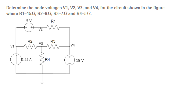

Transcribed Image Text:Determine the node voltages V1, V2, V3, and V4, for the circuit shown in the figure
where R1-15.2, R2=652, R3-72 and R4=5.2.
5 V
V2
R1
w
V1
R2
V3
R3
+
1.25 A
R4
①1.25
V4
15 V
Expert Solution
This question has been solved!
Explore an expertly crafted, step-by-step solution for a thorough understanding of key concepts.

Step by stepSolved in 2 steps with 4 images

Knowledge Booster

Similar questions
- Please someone help me to slove these two problems, and give me an explanation , thank youarrow_forwardConsider the circuit in the figure. Use the included current directions (arrows) and component labels. a) Which of the following equations would be the correct equation for the junction labeled c? - I1=I2+I5 - I2=I1+I3 - I1=I2+I3 - I1=I2+I4 B) Which of the following equations would be the correct equation for the junction labeled d? - I3=I4+I5 - I3+I4=I6 - I3+I4=I5 - I3+I5=I4 C)Which equation for the junction labeled g? - I6+I5=I4 - I6+I4=I5 - I6+I4=I6 - I6=I4+I5 D) Now you have the junction specifying each current. What is the accurate representation of the loop a=>b=>c=>h=>a? E) What is the accurate representation of the loop equation a=>b=>c=>d=>g=>h=>a? F)What is the accurate representation of the loop equation for loop d=>e=>=>g=>d? (Make sure you follow the directions of the currents drawn)arrow_forwardR₁ =1292 Igc = 0.16A IDC = Problem #21) Determine the source current Ipc and the resistor voltage V4 as shown in the following circuit using the Reduce and Return Method if the source voltage is Vpc = 72 volts. R₂=402 R₁ =1552 R₁=4592 0.16 IDC =. V₁=. 2 (A) 36 (A) (V)arrow_forward
- Consider the circuit shown in below Figure, Find values of the resistances R1 and R2 that cause the voltages v1 and v2 to be v1 = 1 V and v2 = 2 V. 500 2 + + R1 R2 () 5 mA 3 mA V1 V2 6:03 PM 50°F Clear 2/18/2022 P Type here to search Del End F10 PgUp. F11 PgDn F12 PrtScn Home F7 F2 F3 F1 & ) Backspace %23 %24 % 4. 5 7 8. 9. 2 3 W.arrow_forwardShown in the figure below is an electrical circuit containing three resistors and two batteries. I₁ 0= 4 + L . ww R3 R₂ ww 1₂ R₁ ww Write down the Kirchhoff Junction equation and solve it for I, in terms of I₂ and I3. Write the result here: 1₁ = 12-13 R₂=552 R₂ = 132 13 Write down the Kirchhoff Loop equation for a loop that starts at the lower left corner and follows the perimeter of the circuit diagram clockwise. - IzR3 − LR₁ + 14 + 10 Write down the Kirchhoff Loop equation for a loop that starts at the lower left corner and touches the components 4V, R₂, and R₁. 0 = 4-1₂R₂-11R₁ The resistors in the circuit have the following values: R₁ = 12 Solve for all the following (some answers may be negative): I₁ = 27.78 X Amperes 1₂ = 28.84 X Amperes 13 = 1.060 X Amperes NOTE: For the equations, put in resistances and currents SYMBOLICALLY using variables like R₁,R₂,R3 and 11,12,13. Use numerical values of 10 and 4 for the voltages.arrow_forwardDesign a circuit that will have an outcome of the highest equivalent resistance across the terminals with a 30Vdc source. Given that the R1 = 10 R2 = 50 R3 = 85. Determine the equivalent resistance from the combination of resistors, R123, R12, R23, and R1.arrow_forward
- Shown in the figure below is an electrical circuit containing three resistors and two batteries. 13 www R₁ ww R3 R₂ www 1₂ • R₁ =90 • R₂ = 60 • R₂ = 10 Write down the Kirchhoff Junction equation and solve it for I, in terms of 12 and 13. Write the result here: I₁ = Write down the Kirchhoff Loop equation for a loop that starts at the lower left corner and follows the perimeter of the circuit diagram clockwise. 0 = X The resistors in the circuit have the following values: 10 Write down the Kirchhoff Loop equation for a loop that starts at the lower left corner and touches the components R₁, R₂, and 4V. 0=R₁₁+R₂1₂-4 Amperes Amperes Amperes 4 Solve for all the following (some answers may be negative): I₁ = 1₂ = | 13 = NOTE: For the equations, put in resistances and currents SYMBOLICALLY using variables like R₁,R₂,R3 and 1₁,12,13. Use numerical values of 10 and 4 for the voltages.arrow_forwardConsider the series-parallel circuit shown in the figure below with various multimeters connected in the circuit. Assum that XMM1 has been configured in ammeter mode, and XMM2 has been configured in voltmeter mode. XMM1 R1 1kQ XMM2 R2 R3 V1 1kQ 1kQ 12V 3.1: Redraw the circuit replacing XMM1 and XMM2 by their equivalent circuit models 3.2: Assume that XMM2 was incorrectly configured in ammeter mode. Redraw the equivalent circuit from 3.1 and compute the current that would be measured by the ammeter in this scenario. Hil-arrow_forwardFor R1=10, R2=5, R3=15, R4=19, R5=4, R6=10, R7=8 and V1=140 V in the Figure, find the following: R1 R7 R4 ŽR2 V1 R6 3R3 ŽR5 ig= and then use current division to find i0=arrow_forward
- The purpose of this problem is to demonstrate that you know how to apply Kirchoff's Rules, you are not required to actually solve for the currents. Knowns: V, R1, R2, R3, R4 a) Label all the currents in the circuit. b) Draw and label all possible closed loops. c) Label each node. d) Apply Kirchoff's Loop rule to all of your labeled loops (set up the equations for each loop). e) Apply Kirchoff's Node rule to all of your labeled nodes (set up the equations for each node). Extra credit: Find the values for your labeled currents using any method you choose R2 R, R, 6V 3V R,arrow_forward3Draw the circuit diagram an solve using ohms law asap pls 3. Two lamps rated 100W and 200V areconnected in series across 200V supply . Find the power consumed by each lamparrow_forwardDue to the nature of this problem, do not use rounded intermediate values in your calculations-including answers submitted in WebAssign. Find the currents flowing in the circuit in the figure below. (Assume the resistances are R, -80, R, 150, A, 60, R200, -0.50,₂-0.75 0,₂-0.250, and r,-0.50) 1₁-0.54 XA 1₂-10288 1,-08268 ХА ХА A₁ www ₁-18V www 4 R₂ £₂ 5 ls 3.0V www 24 VI 12Varrow_forward
arrow_back_ios
SEE MORE QUESTIONS
arrow_forward_ios
Recommended textbooks for you
- Introductory Circuit Analysis (13th Edition)Electrical EngineeringISBN:9780133923605Author:Robert L. BoylestadPublisher:PEARSON
 Delmar's Standard Textbook Of ElectricityElectrical EngineeringISBN:9781337900348Author:Stephen L. HermanPublisher:Cengage Learning
 Programmable Logic ControllersElectrical EngineeringISBN:9780073373843Author:Frank D. PetruzellaPublisher:McGraw-Hill Education
  Fundamentals of Electric CircuitsElectrical EngineeringISBN:9780078028229Author:Charles K Alexander, Matthew SadikuPublisher:McGraw-Hill Education
 Electric Circuits. (11th Edition)Electrical EngineeringISBN:9780134746968Author:James W. Nilsson, Susan RiedelPublisher:PEARSON
 Engineering ElectromagneticsElectrical EngineeringISBN:9780078028151Author:Hayt, William H. (william Hart), Jr, BUCK, John A.Publisher:Mcgraw-hill Education,
Introductory Circuit Analysis (13th Edition)
Electrical Engineering
ISBN:9780133923605
Author:Robert L. Boylestad
Publisher:PEARSON
Delmar's Standard Textbook Of Electricity
Electrical Engineering
ISBN:9781337900348
Author:Stephen L. Herman
Publisher:Cengage Learning
Programmable Logic Controllers
Electrical Engineering
ISBN:9780073373843
Author:Frank D. Petruzella
Publisher:McGraw-Hill Education
Fundamentals of Electric Circuits
Electrical Engineering
ISBN:9780078028229
Author:Charles K Alexander, Matthew Sadiku
Publisher:McGraw-Hill Education
Electric Circuits. (11th Edition)
Electrical Engineering
ISBN:9780134746968
Author:James W. Nilsson, Susan Riedel
Publisher:PEARSON
Engineering Electromagnetics
Electrical Engineering
ISBN:9780078028151
Author:Hayt, William H. (william Hart), Jr, BUCK, John A.
Publisher:Mcgraw-hill Education,