Elements Of Electromagnetics
7th Edition
ISBN: 9780190698614
Author: Sadiku, Matthew N. O.
Publisher: Oxford University Press
expand_more
expand_more
format_list_bulleted
Concept explainers
Question
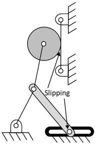
Calculate the mobility of the kinematic chain please

Transcribed Image Text:Slipping
Expert Solution
This question has been solved!
Explore an expertly crafted, step-by-step solution for a thorough understanding of key concepts.
Step by stepSolved in 3 steps with 2 images

Knowledge Booster
Learn more about
Need a deep-dive on the concept behind this application? Look no further. Learn more about this topic, mechanical-engineering and related others by exploring similar questions and additional content below.Similar questions
- QUESTION 1 Consider a 2 DOF system shown below. X1 k₁ m1 F₁ k₂ X2 k3 m₂ F2 The modeshape can be written as (1))] What is x for the second modeshape? Use scientific notation with 3 significant digits and omit units. (eg. -0.123) Let m1 = 2, m2 = 2, k1 = 9, k2 = 8, and k3 = 8.arrow_forwardherr solving pls very urgentarrow_forwardi need to solve part b pls quickk very urgent part (a) is solvedarrow_forward
- find principle following figure момель of # thearrow_forwardFigure P6-29 shows a drum pedal mechanism. O2A = 100 mm at 162° and rotates to 171° at A°. 0204 = 56 mm, AB = 28 mm, AP = 124 mm, and 04B = 64 mm. The distance from 04 to Fin is 48 mm. Find and plot the mechanical advantage and the velocity ratio of the linkage over its range of motion. If the input velocity Vin is a constant magnitude of 3 m/ see, and Fin is constant at 50 N, find the output velocity and output force over the range of motion and the power in.arrow_forwardProblem 3: The RPH robot of Figure 3 is shown in its zero position. Determine the end- effector zero position configuration M, and the screw axes S; in {s}. n. F -inta. Sorowo- Zs {s} Xs L₁ ŷs Lo 0₁5 L2 02 {b} zb 103 pitch h = 0.1 m/rad Ấb ŷb L3 Figure 3: An RPH open chain shown at its zero position. All arrows along/about the joint axes are drawn in the positive direction (i.e., in the direction of increasing joint value). The pitch of the screw joint is 0.1 m/rad, i.e., it advances linearly by 0.1 m for every radian rotated. The link lengths are Lo = 4, L₁= 3, L2= 2, and L3= 1 (figure not drawn to scale).arrow_forward
- 4. A general fourbar linkage configuration and its notation are shown in the following figure and table. Find a 3, a 4,A¼, ABA, AB,Ap for open circuit by vector loop method. Row Link 1 Link 2 Link 3 Link 4 02 Rpa 63 6 2 7 9 30 10 6 30 - 12 - 15 7 3 8 85 25 3 10 6 8 45 -10 10 80 d 7 25 24 - 4 45 e 75 -50 10 300 Rp B A 03 2 X 04 NO O55arrow_forwardA DC servomotor drives the y-axis of a NC milling machine table. The motor is coupled to the table lead screw with a gear reduction of 2:1. The lead screw pitch =5 mm/rev. An optical encoder is directly connected to the lead screw. The optical encoder emits 100 pulse/rev. To execute a certain programmed instruction, the table must move from point (25,28)mm to point (155,275)mm in a straight-line trajectory at a feed rate = 200 mm/min. For the y-axis only, determine: (a) rotational speed of the motor, and (c) frequency of the pulse train emitted by the optical encoder at the desired feed ratearrow_forwardFor the 3-DOF Industrial manipulator arm as shown in Figure 1, determine the joint displacements using inverse kinematics approach for known position and orientation of the end of the arm point. The link transformation matrices are given byarrow_forward
- Obtain the kinematics of the mechanism indicating the variables, inputs and unknowns.arrow_forwardwriting in paper pleasearrow_forwardThe location of the tool, VT, is not accurately known. Using force control, the robot feels around with the tool tip until it inserts it into the socket (or Goal) at location ST. Once in this "calibration" configuration (in which {G}and {T) are coincident), the position of the robot, T, is derived by reading the joint angle sensors and computing the kinematics. Assuming T and Tare known, give the transform equation to compute the unknown tool frame, WT. {B} {S} {W} 2G {G} ÎT {T} ☆G XT 2Tarrow_forward
arrow_back_ios
SEE MORE QUESTIONS
arrow_forward_ios
Recommended textbooks for you
 Elements Of ElectromagneticsMechanical EngineeringISBN:9780190698614Author:Sadiku, Matthew N. O.Publisher:Oxford University Press
 Mechanics of Materials (10th Edition)Mechanical EngineeringISBN:9780134319650Author:Russell C. HibbelerPublisher:PEARSON
 Thermodynamics: An Engineering ApproachMechanical EngineeringISBN:9781259822674Author:Yunus A. Cengel Dr., Michael A. BolesPublisher:McGraw-Hill Education
 Control Systems EngineeringMechanical EngineeringISBN:9781118170519Author:Norman S. NisePublisher:WILEY
 Mechanics of Materials (MindTap Course List)Mechanical EngineeringISBN:9781337093347Author:Barry J. Goodno, James M. GerePublisher:Cengage Learning
 Engineering Mechanics: StaticsMechanical EngineeringISBN:9781118807330Author:James L. Meriam, L. G. Kraige, J. N. BoltonPublisher:WILEY

Elements Of Electromagnetics
Mechanical Engineering
ISBN:9780190698614
Author:Sadiku, Matthew N. O.
Publisher:Oxford University Press

Mechanics of Materials (10th Edition)
Mechanical Engineering
ISBN:9780134319650
Author:Russell C. Hibbeler
Publisher:PEARSON

Thermodynamics: An Engineering Approach
Mechanical Engineering
ISBN:9781259822674
Author:Yunus A. Cengel Dr., Michael A. Boles
Publisher:McGraw-Hill Education

Control Systems Engineering
Mechanical Engineering
ISBN:9781118170519
Author:Norman S. Nise
Publisher:WILEY

Mechanics of Materials (MindTap Course List)
Mechanical Engineering
ISBN:9781337093347
Author:Barry J. Goodno, James M. Gere
Publisher:Cengage Learning

Engineering Mechanics: Statics
Mechanical Engineering
ISBN:9781118807330
Author:James L. Meriam, L. G. Kraige, J. N. Bolton
Publisher:WILEY