A uniform stone slab weighs 400 lb and is suspended by 3 cables and subjected to a downward vertical load as shown in the figure and parameter table.


Q: n the figure shown, the cutaway view shows a solid aluminum alloy of L= 600mm, A= 707mm^2 and E=…
A:
Q: Situation 5: A segment of a chain link is shown in the figure. D. A. If the diameter D is equal to…
A: Solution 5: Part (a) The diameter of the chain, d = 0.25 in. Allowable tensile stress, σallow = 2.5…
Q: Consider the frame shown in Fig 4. A 100N load is suspended around a fixed drum with radius 2 m…
A:
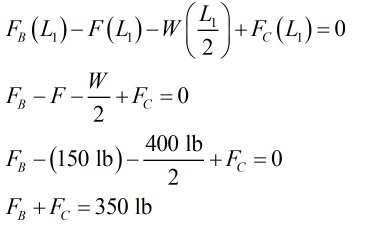
Q: 4. The system of knotted cords shown in Fig P-317 support the indicated weights. Compute the tensile…
A: Given data Given force system in the string
Q: The three bars shown in fig are pined at point B which carry a load P and fixed at points A, C and D…
A:
Q: Consider the frame shown in Fig 4. A 100N load is suspended around a fixed drum with radius 2 m…
A:
Q: The figure above illustrates a system comprising a rigid support structure having a cross-sectional…
A:
Q: A square tie bar 20 mm x 20 mm in section carries a load. It is attached to a bracket by means of 6…
A:
Q: The frame shown in the provide figure has Load F applied at point D. Answer the following questions…
A: Given: The applied force F is 600 N.
Q: Problem 3. The tension lock shown at the figure below will be loaded by an axial force F = 10 kN.…
A:
Q: A bar having two cross sectional areas is loaded by an axial force (P). Part AB and BC are circular…
A:
Q: The figure below is a schematic drawing of a shaft that supports two V-belt pulleys. The loose belt…
A: Given, The yield strength of the material, sy=300 MPa The ultimate strength of the material, su=520…
Q: The rigid beam AD shown carries a load W = 200 kN. It is supported by a hinge at D, a steel rod at…
A:
Q: (b) a. A member ABCD is subjected to point loads as shown in figure Task 2.b. Calculate (i) Force P…
A:
Q: An angle bracket having a thickness t=0.75 in. is attached to the flange of a column by two 5/8-inch…
A: Given data, Thickness of the bracket, t = 0.75 in Diameter of the bolt, db = 0.625 in Pressure on…
Q: G2// The bar AB is considered to be absolutely rigid and is horizontal before the load of 8000 N is…
A:
Q: (a) The column shown in Figure Q3 below is constructed from high-strength concrete and six steel…
A:
Q: Situation 4 - A load of W = 30 Li L2 kN is lifted through a boom BCD as shown in the Figure AP-4.10.…
A: Draw sketch to determine angle using properties of triangles In triangle ABD Angle ADB = 30o (sum…
Q: 13)The Beam in figure below is weightless. A moveable weight(mass)W of 300 Ibm is to be attached as…
A:
Q: Problem 1 An angle bracket ABC is restrained by a high strength steel wire CD, and it supports a…
A: Free body diagram: Equillibrium of Frame ABC:∑MB=0-(1 KN)(cos15)(100)+Tw*90=0Tw=1.0733…
Q: shows a rigid bar AD is supported by the pin-connected rod BC. A uniform distributed load 4 kN/m is…
A: We are authorized to answer three subparts at a time, since you have not mentioned which part you…
Q: Problem B-3 [Design Problem – Simple Loading/2D] A simply supported structure is composed of two…
A:
Q: Draw a Free-Body Diagram of the bars AD and BC shown in the figure. Assume all hinges to be smooth…
A:
Q: 5. An angle bracket ABC is restrained by a high- strength steel wire CD, and it supports a load P at…
A:
Q: As shown in Fig, there is a gap between the aluminum bar and the rigid slab that is supported by two…
A: Given data as per question Area of copper rod =500 mm2 Area of aluminium rod =400 mm2 we know that…
Q: PROBLEMS Figure 1. In the figure shown, a bar ABC with negligible mass carries a 20 kN load and is…
A: Draw FBD
Q: PROBLEM: 4 A helical spring is made from a wire of 11 mm diameter and is of outside diameter 101 mm.…
A: Given: wire diameter, d=11 mmoutside diameter, D=101 mmactive coils , Na=8permissible shear stress,…
Q: -1m 1m Ql: A: Draw a Free-Body Diagram of the bars AD and BC shown in the figure. Assume all hinges…
A:
Q: An aluminum bar having a cross-sectional area of 160 mm2 carries the axial loads at the positions…
A: given data: A= 160mm2 E= 70Gpa Need to determine the total deformation of the bar
Q: 2. The figure shows a spring chair. The chair weight is 100 N. The spring free-length is 500 mm,…
A:
Q: Figure Q2 shows a shaft consists of Rods AB, BC and CD which made of Aluminium, Brass and Steel,…
A:
Q: 1. The homogeneous bar shown in Fig. P-106 is supported by a smooth pin at C and a cable that runs…
A: Given Weight, W = 40 kN Diameter, d = 25 mm = 0.025 m Length, AB = 4 m…
Q: Problem 1 An angle bracket ABC is restrained by a high strength steel wire CD, and it supports a…
A:
Q: For the figure shown below, compute the shear force in section 1. Neglect the weights of the member.…
A:
Q: load of F=1433 kgf will be hung on a Workshop crane as in the figure. The pole to be used has a…
A:
Q: 5. An angle bracket ABC is restrained by a high- strength steel wire CD, and it supports a load P at…
A:
Q: The homogeneous bar AB weighing 2000 lb. is supported at either end by a steel cable. Calculate the…
A:
Q: G2// The bar AB is considered to be absolutely rigid and is horizontal before the load of 8000 N is…
A:
Q: 1. A rigid horizontal bar of negligible mass is connected to two rods as shown in the figure. If the…
A:
Q: Calculate the maximum load (P) that can be supported by the knuckle joint that shown in the figure…
A:
Q: A bracket is attached to a vertical column by means of six identical bolts as shown in Fig. It is…
A: Given-
Q: A car weighing 130 kN when fully loaded is pulled slowly up a steep inclined track by a steel cable…
A: Given Data The weight of the car is: W=130 kN=130000 N The cross sectional area of the cable is:…
Q: Find the stresses in members BC, BD, and CF for the truss shown in Fig. P-113. Indicate the tension…
A: Given data Given truss system A=1300mm2
Q: The bar AB in figure "a" has weight W, length L, and is articulated at point B. End A is supported…
A:
Q: Problem (01): The pin-jointed truss in Figure (6) supports a load of P-2 kips at joint C. Determine…
A:
Q: A car weighing 130 kN when fully loaded is pulled slowly up a steep inclined track by a steel cable…
A: Data given-
Q: PROBLEM 2. The carrier system in the figure consists of the AB rigid beam and two aluminum bars and…
A:
Q: the figure is a b0x with weight W supp0rted by cables at B and C If the maximum stress in either…
A:


From the moment about the x-axis,

Trending now
This is a popular solution!

Step by step
Solved in 4 steps with 5 images


- A uniform bar AB of weight W = 25 N is supported by two springs, as shown in the figure. The spring on the left has a stiffness k[= 300 N/m and natural length Lt=250 mm. The corresponding quantities for the spring on the right are k2= 400 N/m and L^ = 200 mm. The distance between the springs is L = 350 mm, and the spring on the right is suspended from a support that is a distance it = SO mm below the point of support for the spring on the left. Neglect the weight of the springs. (a) At what distance x from the left-hand spring (figure part a) should a load P = 18 N be placed in order to bring the bar to a horizontal position? (b) If P is now removed, what new value of k{is required so that the bar (figure part a) will hang in a horizontal position underweight If? (c) If P is removed and kt= 300 N/m. what distance b should spring ktbe moved to the right so that the bar (figure part a) will hang in a horizontal position under weight II"? (d) If the spring on the left is now replaced by two springs in series (kt= 300 N/m, kt) with overall natural length Lt= 250 mm (see figure part b). what value of k; is required so that the bar will hang in a horizontal position under weight IF?Solve the preceding problem for the following data: b = 6 in., b = 10 in, L = 110 ft, tan a = 1/3, and q = 325 lb/ft.The device shown in the figure consists of a prismatic rigid pointer ABC supported by a uniform translational spring of stiffness k = 950 N/m. The spring is positioned a distance P = 165 nun from the pinned end A of the pointer. The device is adjusted so that, when there is no load P, the pointer reads zero on the angular scale. (a) If the load P = 11 N, al what distance .v should the load be placed so that the pointer will read ?? = 2.5° on the scale (see figure part a)? (b) Repeal part (a) if a rotational spring E1= kb-6 is added al A (see figure part b). (c) Lel.x = 7b/8.What is P maxif 0 cannot exceed 2"? Include spring krin your analysis. (d) Now, if the weight of the pointer ABC is known to be W =3N and the weight or the spring is Ws= 2.75 N, what initial angular position (Left in degrees) of the pointer will result in a zero reading on the angular scale once the pointer is released from rest? Assume P = kr=0. (e) If the pointer is rotated lo a vertical position (see figure part c), find the required load P applied at mid-height of the pointer that will result in a pointer reading of 0 = 2.5" on the scale. Consider the weight of the pointer W. in your analysis.
- A 150-lb rigid bar AB. with friction less rollers al each end. is held in the position shown in the figure by a continuous cable CAD. The cable is pinned at C and D and runs over a pulley at A. (a) Find reactions at supports A and B. (b) Find the force in the cable..15 A hitch-mounted bicycle rack is designed to carry up to four 30-lb bikes mounted on and strapped to two arms Gil (sec bike loads in the figure part a) The rack is attached to the vehicle at A and is assumed to be like a cant silkier beam A BCDGII (figure part b) The light of fixed segment AB is U = 10 lb. centered 9 in. from A (see figure part b) and the rest of the rack highs W2 = 40 lb. centered 19 in. from A. Segment ABCDG is a steel tube o(2 X 2 in. with a thickness I = 118 in. Segment BCDGII pivots about a bolt at B with a diameter d1 = 0.25 in. to allow access to the rear of the vehicle without removing the hitch rack. When in use, the rack is secured in an upright posit ion by a pin C(diameter o( pin d, = 5116 in.) (see phoo and figure part C). The of returning effect of the bikes on the rack is resisted by a force couple F h at BC. (a) Find the support reactions at A for the fully loaded rack. (b) Find forces in the bolt at B and the pin at C. (c) Find average shear stresses in both the bolt at Band the pin at C. (d) Find average bearing stresses o, in the bolt at B and the pin at C..17 A mountain-bike rider going uphill applies torque T = Fd(F = l5lb, d = 4 in.) to the end of the handlebars ABCD by pulling on the handlebar extenders DE. Consider the right half of the handlebar assembly only (assume the bars are fixed at the fork at A). Segments AB and CD are prismatic with lengths L, = 2 in.andL3 = 8.5 in, and with outer diameters and thicknesses d01 = 1.25 in. 101 = 0.125 in. and d03 = O.87in.,i03 = 0.ll5in, respectively as shown. Segment BC’ of length L, = 1.2 in. however. is tapered, and outer diameter and thickness vary linearly between dimensions at B and C. Consider torsion effects only. Assume G = 4000 ksi is constant. Derive an integral expression for the angle of twist of half of the handlebar tube when it is subjected to torque T = Fd acting at the end. Evaluate ‘b1-, for the given numerical1ues.
- Solve the preceding problem if the collar has mass M = 80 kg, the height h = 0.5 m, the length L = 3.0 m, the cross-sectional area A = 350mm2. and the modulus of elasticity E = 170 GPa.The L-shaped arm ABCD shown in the figure lies in a vertical plane and pivots about a horizontal pin at A. The arm has a constant cross-sectional area and total weight W. A vertical spring of stiffness k supports the arm at point B. (a) Obtain a formula for the elongation of the spring due to the weight of the arm. (b) Repeat part (a) if the pin support at A is moved to D.By what distance h does the cage shown in the figure move downward when the weight W is placed inside it? (See the figure.) Consider only the effects of the stretching of the cable, which has axial rigidity EA = 10,700 kN. The pulley at A has a diameter da= 300 mm and the pulley at B has a diameter dB= 150 mm. Also, the distance L1= 4.6 m, the distance L2=10.5 m, and the weight W = 22 kN. Note: When calculating the length of the cable. include the parts of the cable that go around the pulley sat A and B.
- A safety valve on the top of a tank containing steam under pressure p has a discharge hole of diameter d(see figure). The valve is designed to release the steam when the pressure reaches the value Pmax If the natural length of the spring, is L and its stiffness is k, what should be the dimension ft of the valve? (Express your result as a formula for h.)Solve the preceding problem for W = 1.0 lb. h = 12 in.,and k =0.511,/in.A polyethylene tube (length L) has a cap that when installed compresses a spring (with under-formed length L1) by an amount ?? = (L1 = L). Ignore deformations of the cap and base. Use the force at the base of the spring as the redundant. Use numerical properties given in the boxes. (a) What is the resulting Force-in the spring, Fk? (b) What is the resulting Force in the tube, Ftl (c) What is the filial length of the tube, Lf? (d) What temperature change ?T inside the tube will result in zero force in the spring