
Mechanics of Materials (MindTap Course List)
9th Edition
ISBN: 9781337093347
Author: Barry J. Goodno, James M. Gere
Publisher: Cengage Learning
expand_more
expand_more
format_list_bulleted
Related questions
Question
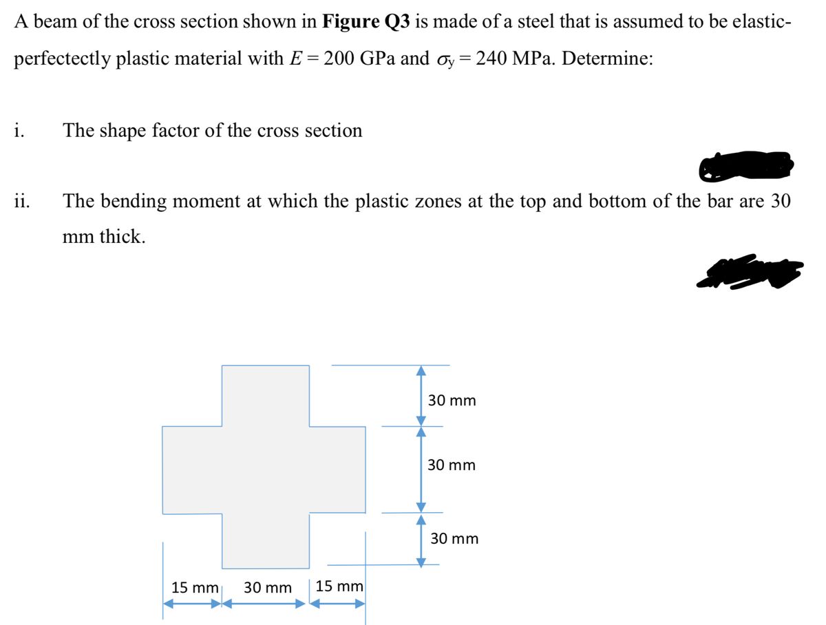

Transcribed Image Text:A beam of the cross section shown in Figure Q3 is made of a steel that is assumed to be elastic-
perfectectly plastic material with E = 200 GPa and σy = 240 MPa. Determine:
i.
The shape factor of the cross section
ii.
The bending moment at which the plastic zones at the top and bottom of the bar are 30
mm thick.
15 mm
30 mm
15 mm
30 mm
30 mm
30 mm
Expert Solution
This question has been solved!
Explore an expertly crafted, step-by-step solution for a thorough understanding of key concepts.

Step by stepSolved in 2 steps with 5 images

Knowledge Booster

Similar questions
- The cross section of a sand wie h beam consisting of aluminum alloy faces and a foam core is shown in the figure. The width b of the beam is 8.0 in, the thickness I of the faces is 0.25 in., and the height hcof the core is 5.5 in. (total height h = 6.0 in). The moduli of elasticity are 10.5 × 10⁶ psi for the aluminum faces and 12.000 psi for the foam core. A bending moment M = 40 kip-in. acts about the z axis. Determine the maximum stresses in the faces and the core using (a) the general theory for composite beams and (b) the approximate theory for sandwich beams.arrow_forwardThe length of the end segments of the bar (see figure) is 20 in. and the length of the prismatic middle segment is 50 in. Also, the diameters at cross sections A. B, C, and D are 0.5, 1.0, 1.0, and 0.5 in., respectively, and the modulus of elasticity is 18 ,000 ksi. (a) Calculate the elongation of a copper bar of solid circular cross section with tapered ends when it is stretched by axial loads of magnitude 3.0 kips (see figure). (b) If the total elongation of the bar cannot exceed 0.025 in., what are the required diameters at B and C? Assume that diameters at A and D remain at 0.5 in.arrow_forwardThe cross section of a sandwich beam consisting of fiberglass faces and a lightweight plastic core is shown in the figure. The width b of the beam is 50 mm, the thickness I of the faces is 4 mm, and the height hcof the core is 92 mm (total height A = 100 mm). The moduli of elasticity are 75 GPa for the fiberglass and 1.2 GPa for the plastic. A bending moment M = 275 N · m acts about the z axis. Determine the maximum stresses in the faces and the core using (a) the general theory for composite beams and (b) the approximate theory for sandwich beams.arrow_forward
- A plastic-lined steel pipe has the cross-sectional shape shown in the figure. The steel pipe has an outer diameter d1= 100 mm and an inner diameter d2= 94 mm. The plastic liner has an inner diameter d1= 82 mm. The modulus of elasticity of the steel is 75 times the modulus of the plastic. Determine the allowable bending moment Mallowif the allowable stress in the steel is 35 M Pa and in the plastic is 600 kPa. If pipe and liner diameters remain unchanged, what new value of allowable stress for the steel pipe will result in the steel pipe and plastic liner reaching their allowable stress values under the same maximum moment (i.e., a balanced design)? What is the new maximum moment?arrow_forwardThe cross section of a beam made of thin strips of aluminum separated by a lightweight plastic is shown in the figure. The beam has width b = 3.0 in., the aluminum strips have thickness t = 0.1 in., and the plastic segments have heights d = 1.2 in. and 3d = 3.6 in. The total height of the beam is h = 6.4 in. The moduli of elasticity for the aluminum and plastic are EM= 11 X 106 psi and Ep= 440 X 10* psi, respectively. Determine the maximum stresses trAiand pin the aluminum and plastic, respectively, due to a bending moment of 6,0 kip-in.arrow_forwardThe Z-section of Example D-7 is subjected to M = 5 kN · m, as shown. Determine the orientation of the neutral axis and calculate the maximum tensile stress c1and maximum compressive stress ocin the beam. Use the following numerical data: height; = 200 mm, width ft = 90 mm, constant thickness a = 15 mm, and B = 19.2e. Use = 32.6 × 106 mm4 and I2= 2.4 × 10e mm4 from Example D-7arrow_forward
- A flat brass bar has length L, constant thickness t, and a rectangular cross section whose width varies linearly between b2at the fixed support to b1at the free end (see figure). Assume that the taper of the bar is small. The bar has modulus of elasticity E. Calculate the displacements ??Band ??cif P = 200 kN, L = 2 m, t = 20 mm, b, = 100 mm, b, = 115 mm, and E = 96 GPa.arrow_forwardThe external loads on the element shown below at the free end are F = 1.75 kN, P = 9.0 kN, and T = 72 Nm. The tube's outer diameter is 50 mm and the inner diameter is 45 mm. Given: A(the cross-sectional area) is 3.73 cm², Moment inertial I is 10.55 cm4, and J polar moment inertial is 21.1 cm4. Determine the following. (1) The critical element(s) of the bar. (2) Show the state of stress on a stress element for each critical element. -120 mm- Farrow_forwardThe channel shape cross-section and the rectangular cross-section shown in the Figure Q4 are made of materials with elastic-perfectly plastic behaviour. The yield stress of the material used for the channel shape cross-section is σy = 449 MPa, whereas that used for the rectangular cross- section is 0.7%y. Compute the thickness of the web, t, of the channel shape section if the two cross sections have identical plastic bending moment about the z-axis. In Figure 4, h= 96 mm, b=43 mm, a=12 mm, H=96 mm, d= 43 mm N b h a Z a | d Harrow_forward
- A beam has a bending moment of 3.5 kN-m applied to a section with a hollow circular cross-section of external diameter 3 cm and internal diameter 2.3 cm . The modulus of elasticity for the material is 210 x 109 N/m2. Calculate the radius of curvature and maximum bending stress. Also, calculate the stress at the point at 0.6 cm from the neutral axis (i) The moment of inertia in (mm^4)= ii) The radius of curvature in (mm) = (iii) The maximum bending stress in (N/mm^2)= iv) The bending stress at the point 0.6 cm from the neutral axis in (N/mm^2)=arrow_forwardThe figure below shows the cross-section of an axisymmetric composite beam that comprises steel (Young's modulus 270 GPa) and aluminum (Young's modulus 90 GPa) sections that are bonded together. The steel section is of wall thickness 15 mm and the aluminum section is of wall thickness 10mm. The steel section comprises 4 axisymmetric holes of 5 mm diameter as shown. Given that the beam is bent by a couple moment of 1200 Nm, determine the maximum stress in steel and aluminum. 4 holes of diameter 5 mm. 12 mm steel aluminumarrow_forwardA bar ABC of length L consists of two parts of equal lengths but different diameters. Segment AB has a diameter d 1 = 100 mm and segment BC has a diameter d 2 = 60 mm. Both segments have a length L / 2 = 0.6 m. A longitudinal hole of diameter d is drilled through segment AB in the middle of its length (distance L / 4 = 0.3 m). The bar is made of plastic with a modulus of elasticity. E = 4.0 GPa. Compressive loads P = 110 kN act at the ends of the bar. (a) If the shortening of the bar is limited to 8.0 mm, what is the maximum allowable diameter d max of the hole? (See figure part a.) (b) Now, if d max is set to d 2/2, at what distance b from the end C must the load P be applied to limit the shortening of the bar to 8.0 mm? (See Figure part b.) (C) Finally, if the loads P are applied at the ends and d max = d 2/2, what is the allowable length x of the hole if shortening is limited to 8.0 mm? (See figure part c.)arrow_forward
arrow_back_ios
SEE MORE QUESTIONS
arrow_forward_ios
Recommended textbooks for you
- Mechanics of Materials (MindTap Course List)Mechanical EngineeringISBN:9781337093347Author:Barry J. Goodno, James M. GerePublisher:Cengage Learning
Mechanics of Materials (MindTap Course List)
Mechanical Engineering
ISBN:9781337093347
Author:Barry J. Goodno, James M. Gere
Publisher:Cengage Learning