Delmar's Standard Textbook Of Electricity
7th Edition
ISBN: 9781337900348
Author: Stephen L. Herman
Publisher: Cengage Learning
expand_more
expand_more
format_list_bulleted
Question

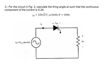
Transcribed Image Text:3.- For the circuit in Fig. 3, calculate the firing angle at such that the continuous
component of the current is 0.3A.
Gp =
220√√2 V, w=2л50, R = 1000.
V=VGp sen (wt)
G
+ "AK -
+
00
Expert Solution
This question has been solved!
Explore an expertly crafted, step-by-step solution for a thorough understanding of key concepts.
Step by stepSolved in 2 steps with 2 images

Knowledge Booster
Similar questions
- The circuit in the figure is fed by a sinusoidal alternating voltage with a frequency of 50 Hz. The circuit consists of a resistor and a capacitor with the capacitance C= 600 μ Q. The power supplied to the circuit is P=400 W and the voltage across capacitor is UC=90 V. a) Calculate the current I. b) Calculate the resistance R. c) Calculate the voltage U (amount). d) Calculate the phase angle of the circuitarrow_forwardThe circuit in the figure is fed by a sinusoidal alternating voltage with a frequency of 50 Hz. The circuit consists of a resistor and a capacitor with the capacitance C= 300 μ Q. The power supplied to the circuit is P=100 W and the voltage across capacitor is UC=120 V. a) Calculate the current I. b) Calculate the resistance R. c) Calculate the voltage U (amount). d) Calculate the phase angle of the circuitarrow_forwardPlease provide a clear solution. Maintain the final answers to 3 decimal places by defaults. Please answer quickly 30 mins left thank you!arrow_forward
- Calculate the branch currents and the total equivalent current of the complete circuit in Figure Q3. Draw the current phasor diagram for the complete circuit. The alternating Voltage source has an amplitude of 10 Vm Sine 50 Hz CI 1 mF C2 1.2 mF Figure Q3 RI 22 52 C3 0.4 mF R2 44 92arrow_forwardQ1 Explain the following terms: (a) Sensor (1.5 marks) (b) Transducer (1.5 marks) (c) Instrument Q2 Q3 (2 marks) Based on Figure Q2, if the RTD sensor measurement is 57°C answer the following. (a) Calculate the output current from RTD sensor if the output range is 4 20mA. (2 marks) (b) Calculate the output voltage from the temperature controller if the output range is 0-10VDC. (2 marks) (c) Propose a type of sensor if the process temperature is increased to 1000°C. (1 marks) A capacitive displacement transducer is designed to determine the rotary position. from 0° 180° as shown in Figure Q3. The moving plate whose radius is 40mm is sandwiched between two fixed plates, spacing at Imm. The dielectric constant of air is k 1.The capacitive transducer is formulated as: where; (a) kA€。 farads k = dielectric constant A the area of the plate, in square meters €₁ = 8.854 × 10⁻¹² in farads per meter d = the plate spacing in meters Construct an equation of the change of the capacitance (F) when…arrow_forwardFor the circuit in the figurea) Determine the time constant.b) Write the mathematical expression for IL, VL and VR, after the switch is closed.c) Determine IL, VL for one, three and five time constants.d) Draw the waveforms of IL, VL and VR.arrow_forward
- Please solve it with all stepsarrow_forwardFrom the given circuit, what is the inductive reactance for the given inductance L (pick the value that is closes to given options). V-15 Vac R-1.5k L-50mH -3.183 kHz 100 ohms 1000 ohms 100,000 ohms 1000,000 ohmsarrow_forwardAnalyze and draw the output waveform of Vo for the following circuits. Identify the type of circuit and label waveform. Write solutions on the pdf file. Summary of answers of Vo on the Google form. Indicate the cycle being analyzed.arrow_forward
- Obtain the equivalent capacitance at terminals a and b of the circuit below. *Round off the final answer to the nearest 4 decimal places with unit. Rounding off should only be done on final answer.arrow_forwardWhen the switch is in position 1, the circuit will charge the capacitor. Find the Thevenin Equivalent Circuit for the charge phase and determine the time constant (Rh*C) for the charge phase.arrow_forwardA capacitor circuit carrying 12 mA is placed across a 9 V sine wave ac source. A resistor carrying 20 mA is connected in parallel with the capacitor. The total circuit magnitude of current is esc 233 mA 32 mA O 12 MA ! 1 20 mA Q A N ← 2 W S #3 C E D X C $ 4 R F G Search or type URL % 5 V T G ^ 6 MacBook Pro B Y H & 7 N U ☆ J * 00 8 M + - ( 9 K < O < ) O L ➡ P V : ; { [ + + 11 = ? 11 F } 1 delete returnarrow_forward
arrow_back_ios
SEE MORE QUESTIONS
arrow_forward_ios
Recommended textbooks for you
 Delmar's Standard Textbook Of ElectricityElectrical EngineeringISBN:9781337900348Author:Stephen L. HermanPublisher:Cengage Learning

Delmar's Standard Textbook Of Electricity
Electrical Engineering
ISBN:9781337900348
Author:Stephen L. Herman
Publisher:Cengage Learning