
Introductory Circuit Analysis (13th Edition)
13th Edition
ISBN: 9780133923605
Author: Robert L. Boylestad
Publisher: PEARSON
expand_more
expand_more
format_list_bulleted
Related questions
Question
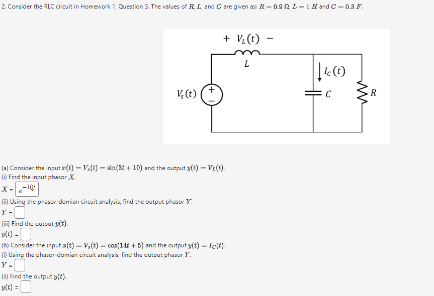

Transcribed Image Text:2. Consider the RLC circuit in Homework 1, Question 3. The values of R, L, and C are given as: R = 0.9 . L = 1 H and C = 0.3 F.
+ V₁(t)
L
V(t)
+
(a) Consider the input x(t) = V,(t) = sin(3t+ 10) and the output y(t) = V₁(t).
(i) Find the input phasor X.
X=-10j
e
(ii) Using the phasor-domian circuit analysis, find the output phasor Y.
Y =
(iii) Find the output y(t).
y(t) = |
(b) Consider the input x(t) = V,(t) = cos(14t+5) and the output y(t) = Ic(t).
(i) Using the phasor-domian circuit analysis, find the output phasor Y.
Y=☐
(ii) Find the output y(t).
v(t) =
-
|| Ic (t)
R
C
Expert Solution
This question has been solved!
Explore an expertly crafted, step-by-step solution for a thorough understanding of key concepts.

Step by stepSolved in 2 steps

Knowledge Booster

Similar questions
- Generate plots for each of the following functions over time span -4s to +4s x1(t)= 5r(t+2)-5r(t)arrow_forwardThe values of the elements of an RLC circuit are given. Solve the initial value problem with the given impressed voltage e(t). di + Ri + dt i(t)dt = e(t), i(0) = 0 L=1, R= 50, C = 1.6x 10; e(t) = 20t if 0st<5, e(t) = 0 if t2 5 Click the icon to view a short table of Laplace transforms. Solve the initial value problem. i(t) =arrow_forwardSOLVE STEP BY STEP IN DIGITAL FORMAT DONT USE CHATGPT 1. Referring to the circuit in the following figure, find: a. i(0*)&v(0*) b. di(0*)/dt & dv(0*)/dt c. i(∞) & v(∞0) 12 V (+ t = 0 692 2 H ele 492 0.4 F www + p -arrow_forward
- Draw SD( state diagram of state equation). See attached examplearrow_forwardC(s) R(s) s+5 to get an overshoot of 15% and a settling time at 2% of 0.5 seconds, The value of damping ratio is Select one: O a. 0.707 O b. 0.417 c. 0,517 O d. 0.69arrow_forward- Determine which of the following function are (even, odd or not) function: 1- f(t) = 3t2 sin(3t) %3D 2 - f(t) = 4t3 + 6 sin(2t) %3D 3 - f(t) = t² sin(2t) cos(3t) f(t) = 2 sin(t²) 4 - 5 - f(t) = t2 + 4 cos (2t) +3 sin(2t)arrow_forward
- Q2) Sketch the following waveforms a) V:(t) = Su(t+2) + 8u(t) - 6u(t-4) b) V2(t) = 50e 200 c) V:(t) = r(t+4) – r(t-3)arrow_forwardDifferential equations Find the steady-state current in an LRC circuit when L = 1/2h , R = 20Ω, C = 0.001f and E(t) = 100sen60t+200cos40t V. Dont skip steps plsarrow_forwardA second order circuit's impulse and step response The figure below shows a series second order RLC circuit. The system input is a step voltage source vin(t) = u(t) and the output is the voltage across resistor R. + Vin(t) C m L i(t). RVout (t) Series RLC As shown in the section regarding second order LCCDES impulse response, the Kirchhoff's voltage law equation can be written as di ½ i(t)dt + L + Ri = vix(t) = u(t). di Differentiating results: + di² Ldt LC d²i Rdi 1 + i= =(t). The circuit's characteristic equation can be written as: = 0. R + = + s+ L LC A system's impulse response can be found using the residue function. Ex: for the LCCDE b₂ d²v + b₁ dy b₁1/4 + bo= αι +ao, dx di [R, P] = residue ([a1 a0], [b2 b1 b0]) Vectors [a1 a0] and [b2 b1 b0] are the input (right hand side) and output (left hand side) coefficients respectively. Vector R contains the residues and vector P contains the roots (poles) of the characteristic equation. If the impulse response has the form h(t) = Aet +…arrow_forward
- Please answer in typing format solution please only typing format solution Please in typing format solution please onlyarrow_forwardplease do all partsarrow_forwarda series connected rlc circuit is shown the switch opens at t=0 iL(t=0+)= ic(t=0+)= vc(t=0+)= vL(t=0+)= diL/dt(t=0+)= dvc/dt(t=0+)= vL(t=inf.)= vR(t=inf.)= vc(t=inf.)=arrow_forward
arrow_back_ios
SEE MORE QUESTIONS
arrow_forward_ios
Recommended textbooks for you
- Introductory Circuit Analysis (13th Edition)Electrical EngineeringISBN:9780133923605Author:Robert L. BoylestadPublisher:PEARSON
 Delmar's Standard Textbook Of ElectricityElectrical EngineeringISBN:9781337900348Author:Stephen L. HermanPublisher:Cengage Learning
 Programmable Logic ControllersElectrical EngineeringISBN:9780073373843Author:Frank D. PetruzellaPublisher:McGraw-Hill Education
  Fundamentals of Electric CircuitsElectrical EngineeringISBN:9780078028229Author:Charles K Alexander, Matthew SadikuPublisher:McGraw-Hill Education
 Electric Circuits. (11th Edition)Electrical EngineeringISBN:9780134746968Author:James W. Nilsson, Susan RiedelPublisher:PEARSON
 Engineering ElectromagneticsElectrical EngineeringISBN:9780078028151Author:Hayt, William H. (william Hart), Jr, BUCK, John A.Publisher:Mcgraw-hill Education,
Introductory Circuit Analysis (13th Edition)
Electrical Engineering
ISBN:9780133923605
Author:Robert L. Boylestad
Publisher:PEARSON
Delmar's Standard Textbook Of Electricity
Electrical Engineering
ISBN:9781337900348
Author:Stephen L. Herman
Publisher:Cengage Learning
Programmable Logic Controllers
Electrical Engineering
ISBN:9780073373843
Author:Frank D. Petruzella
Publisher:McGraw-Hill Education
Fundamentals of Electric Circuits
Electrical Engineering
ISBN:9780078028229
Author:Charles K Alexander, Matthew Sadiku
Publisher:McGraw-Hill Education
Electric Circuits. (11th Edition)
Electrical Engineering
ISBN:9780134746968
Author:James W. Nilsson, Susan Riedel
Publisher:PEARSON
Engineering Electromagnetics
Electrical Engineering
ISBN:9780078028151
Author:Hayt, William H. (william Hart), Jr, BUCK, John A.
Publisher:Mcgraw-hill Education,