
Delmar's Standard Textbook Of Electricity
7th Edition
ISBN: 9781337900348
Author: Stephen L. Herman
Publisher: Cengage Learning
expand_more
expand_more
format_list_bulleted
Related questions
Question
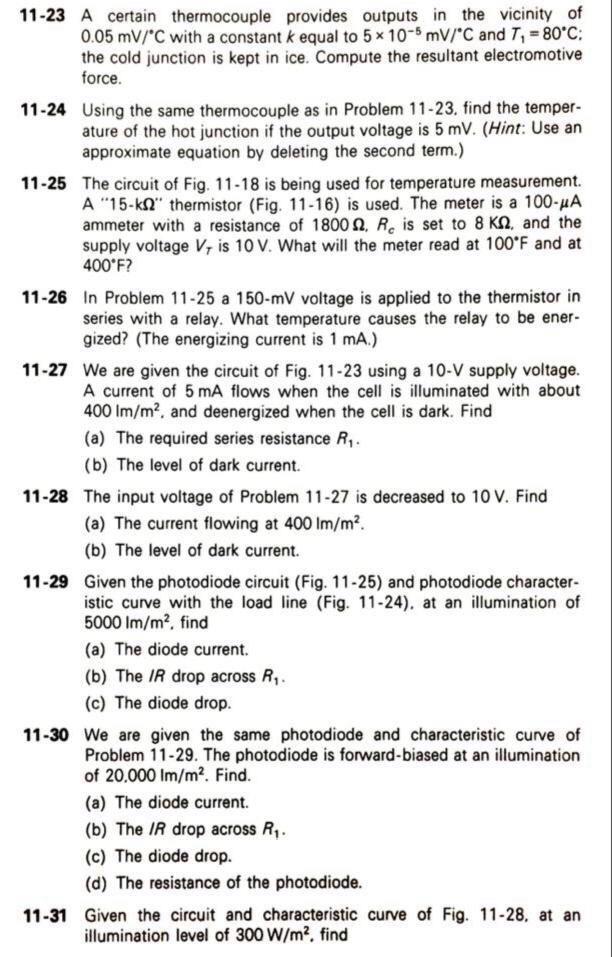

Transcribed Image Text:11-23 A certain thermocouple provides outputs in the vicinity of
0.05 mV/°C with a constant k equal to 5 x 10⁻⁵ mV/°C and 7₁ = 80°C;
the cold junction is kept in ice. Compute the resultant electromotive
force.
11-24 Using the same thermocouple as in Problem 11-23. find the temper-
ature of the hot junction if the output voltage is 5 mV. (Hint: Use an
approximate equation by deleting the second term.)
11-25 The circuit of Fig. 11-18 is being used for temperature measurement.
A "15-k" thermistor (Fig. 11-16) is used. The meter is a 100-μA
ammeter with a resistance of 1800, R is set to 8 KQ, and the
supply voltage V, is 10 V. What will the meter read at 100°F and at
400°F?
11-26 In Problem 11-25 a 150-mV voltage is applied to the thermistor in
series with a relay. What temperature causes the relay to be ener-
gized? (The energizing current is 1 mA.)
11-27 We are given the circuit of Fig. 11-23 using a 10-V supply voltage.
A current of 5 mA flows when the cell is illuminated with about
400 lm/m², and deenergized when the cell is dark. Find
(a) The required series resistance R₁.
(b) The level of dark current.
11-28 The input voltage of Problem 11-27 is decreased to 10 V. Find
(a) The current flowing at 400 lm/m².
(b) The level of dark current.
11-29 Given the photodiode circuit (Fig. 11-25) and photodiode character-
istic curve with the load line (Fig. 11-24). at an illumination of
5000 lm/m², find
(a) The diode current.
(b) The IR drop across R₁.
(c) The diode drop.
11-30 We are given the same photodiode and characteristic curve of
Problem 11-29. The photodiode is forward-biased at an illumination
of 20,000 Im/m². Find.
(a) The diode current.
(b) The IR drop across R₁.
(c) The diode drop.
(d) The resistance of the photodiode.
11-31 Given the circuit and characteristic curve of Fig. 11-28, at an
illumination level of 300 W/m², find
Expert Solution
This question has been solved!
Explore an expertly crafted, step-by-step solution for a thorough understanding of key concepts.

Step by stepSolved in 2 steps

Knowledge Booster

Similar questions
- A 15-F AC capacitor is connected in series with a 50 resistor. The capacitor has a voltage rating of 600 WVDC. The capacitor and resistor are connected to a 480-V, 60-Hz circuit. Is the voltage rating of the capacitor sufficient for this connection?arrow_forwardC'uk Converter Design A C'uk converter has an input of 12 V and is to have an output of - 24 V supplying a 60 W load. Select the duty ratio, the switching frequency, the inductor sizes such that the change in inductor currents is no more than 12 percent of the average inductor current, the output ripple voltage is no more than 1.5 percent, and the ripple voltage across C1 is no more than 3 percent.arrow_forwardPlease solve the marked question.arrow_forward
- An inductance coil consumes 500W of power at 10A and 110V and 60HZ. Determine the resistance and the inductance of the coilarrow_forwardA Capacitor filter is used at the output across the load to minimize the ripple factor of the output voltage. If R = 20 02 and the single- phase bridge rectifier is supplied from a 120V - 60 Hz sinusoidal source. Find the capacitor value in millifarads that will maintain the amount of the output ripples to less than 5% 艹 Ce = m₂ 0 mF RL%arrow_forwardPlease address the question in the attached photo. Thank you.arrow_forward
- Electrical Engineering 1) A sinusoidal signal of 500 mV and 1 kHz from peak to peak is given as the input signal from the function generator. a) Calculate the voltage gain of the circuit in Figure 1. b) What is the phase relationship between input and output signals? (Assume ß = 50 and VBE = 0.4 V) RE 10kO RL 56kO C2 Vout C1 Q1: 10µF 10uF BD139 : Víni RB1: 2.2k0 RB2 : 500 mVpp 1-kHz S0.56kO Figure 1arrow_forwardA capacitor C is connected in parallel with a resistor R across a 120 V, 200 Hz supply. The supply current is 2 A at a power factor of 0.6 leading. Determine the values of C and R.arrow_forwardGiven: Np = 6 turns fin = 54 Hz Ns = 1 turn Vp = 215 Vacarrow_forward
- how many volts q9arrow_forward5/1 IN4001 120 V 60 Hz R 5 k2 100 uF 1) Explain how this circuit works 2) Draw the waveform at the output (Vrl) for a sinusoidal signal at the input 3) What is the effective voltage of peak voltage in the secondary? 4) What is the peak voltage on the load? 5) What is the average voltage of the output (on the load)? 6) Calculate ripple on loadarrow_forwardDuring the positive input cycle shown, the conduction path is through diodes a. Di and D2 b. Dz and D4 D1 D3 c. D1 and D4 Vin d. D2 and D3 D2 D4arrow_forward
arrow_back_ios
SEE MORE QUESTIONS
arrow_forward_ios
Recommended textbooks for you
- Delmar's Standard Textbook Of ElectricityElectrical EngineeringISBN:9781337900348Author:Stephen L. HermanPublisher:Cengage Learning
 Electricity for Refrigeration, Heating, and Air C...Mechanical EngineeringISBN:9781337399128Author:Russell E. SmithPublisher:Cengage Learning
Delmar's Standard Textbook Of Electricity
Electrical Engineering
ISBN:9781337900348
Author:Stephen L. Herman
Publisher:Cengage Learning
Electricity for Refrigeration, Heating, and Air C...
Mechanical Engineering
ISBN:9781337399128
Author:Russell E. Smith
Publisher:Cengage Learning