Power System Analysis and Design (MindTap Course List)
6th Edition
ISBN: 9781305632134
Author: J. Duncan Glover, Thomas Overbye, Mulukutla S. Sarma
Publisher: Cengage Learning
expand_more
expand_more
format_list_bulleted
Question

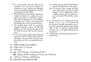
Transcribed Image Text:1. In a coaxial power cable the radius of the
conductor is 25 mm and the thickness of
insulation is 8 mm. Calculate the Schwaiger
factor n in this field configuration. Comment
on uniformity of electric field.
2. What will be the most economical (optimum)
conductor diameter of a single core power
cable to be used on 132 kV power systems?
Also find the diameter over the insulation
provided to the conductor if the maximum
permissible stress is not to exceed 8 kV/mm.
3. Two parallel plates which are oppositely
charged are placed 5 cm apart. The potential
difference, in volts, between the plates is 100
kV. Find the electric field intensity between
them.
4. In a 220 kV rated voltage coaxial spherical
system of a GIS the radius of the inner HV
electrode is 10.0 cm and the SF6 gas insula-
tion thickness of 18.0 cm is provided around.
Find
1. 0.868, weakly non-uniform.
2. 19.04 mm, 51.79 mm
3. 2 kV/mm
4. (a) 19.75 kV/cm, 2.52 kV/cm, 0.357
(a) The max and min electric field intensities
and the Schwaiger factor in the system.
(b) For the given system voltage and fixed
outer radius of the coaxial system, what
changes in the configuration will be
needed to optimise the max field inten-
sity in this system? What will be its value
then?
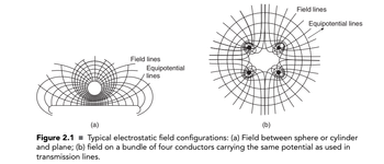
5. If a potential of 5 kV is applied across gap
distance d' of 5 cm in air between (a)
the uniform, (b) weakly nonuniform and (c)
extremely nonuniform field electrode systems
shown in Fig. 2.1, find the maximum field
intensities, Emax at the high-voltage electrode
in each case?
6. In which case is the dielectric properties of air
utilized least?
(b) Radius of HV conductor 14 cm, 18.14 kV/cm
5. 1 kV/cm, 4 kV/cm, 100 kV/cm
6. Extremely non-uniform field

Transcribed Image Text:Field lines
Equipotential
lines
Field lines
Equipotential lines
(a)
(b)
Figure 2.1 ■Typical electrostatic field configurations: (a) Field between sphere or cylinder
and plane; (b) field on a bundle of four conductors carrying the same potential as used in
transmission lines.
Expert Solution
This question has been solved!
Explore an expertly crafted, step-by-step solution for a thorough understanding of key concepts.
Step by stepSolved in 2 steps with 3 images

Knowledge Booster
Similar questions
- Three single-phase, two-winding transformers, each rated 450MVA,20kV/288.7kV, with leakage reactance Xeq=0.10perunit, are connected to form a three-phase bank. The high-voltage windings are connected in Y with a solidly grounded neutral. Draw the per-unit equivalent circuit if the low-voltage windings are connected (a) in with American standard phase shift or (b) in Y with an open neutral. Use the transformer ratings as base quantities. Winding resistances and exciting current are neglected.arrow_forwardIn developing per-unit circuits of systems such as the one shown in Figure 3.10. when moving across a transformer, the voltage base is changed in proportion to the transformer voltage ratings. (a) True (b) Falsearrow_forwardA 33 kV single core cable has a conductor diameter of 1 cm and a sheath of inside diameter 4 cm. Find the maximum and minimum stress in the insulation.arrow_forward
- 2- Draw and explain the phasor diagram for two transformers in parallel.arrow_forwardTwo 11,000/2,200-V, 1-phase transformers are connected in parallel to supply a total load of 200 at 0.8 p.f. lagging at 2,200 V. One transformer has an equivalent resistance of 0.4 ohms and equivalent reactance of 0.8 ohms referred to the low-voltage side. The other has equivalent resistance of 0.1 ohms and a reactance of 0.3 ohms. Determine the current and power supplied by each transformer.arrow_forwardA 10 MVA three phase load is to be served by a three phase transformer at aline voltage of 13.8 kV. The supply side voltage(line-line) is 138 kV. Varioussingle phase transformers are available in the warehouse but all havewindings with voltage ratings under 100 kV and current ratings under 250 A.Is it possible to serve the load using only three single phase transformers? Ifso, specify the three phase connections and the low and high voltage ratingsof the single phase transformers.arrow_forward
- Define all the losses in the transformer with the diagram and then define the hysterisis loss with thw graph.arrow_forwardSubject - Design electrical circuits for single-phase AC networks Question - Compare the effect of varying resistance, capacitance and inductance in parallel and series AC circuits on voltage, resistance and impedancearrow_forwardConsider the three single-phase two-winding transformers shown in Figure. 3. The high-voltage windings are connected in Y. (a) For the low-voltage side, connect the windings in A, and label the terminals a, b, and c in accordance with the American standard. (b) Relabel the terminals a', b', and c' such that VAN is 90° out of phase with V₂'b' for positive sequence. DI H₂ Figure. 3: Three-Winding Transformerarrow_forward
- Three single-phase transformers, each rated 10 MVA , 66.4/12.5 kV, 60 Hz , with an equivalent series reactance of 0.1 per unit divided equally between primary and secondary, are connected in a three-phase bank. The high-voltage windings are Y-connected and their terminals are directly connected to a 115-kV three-phase bus. The secondary terminals are all shorted together. Find the currents entering the high-voltage terminals and leaving the low-voltage terminals if the low-voltage windings are (a) Y-connected and (b) Δ- connected.arrow_forwardThree single-phase two-winding transformers, each rated 3kVA,220/110volts,60Hz, with a 0.10 per-unit leakage reactance, are connected as a three-phase extended autotransformer bank, as shown in Figure 3.36(c). The low-voltage winding has a 110 volt rating. (a) Draw the positive-sequence phasor diagram and show that the high-voltage winding has a 479.5 volt rating. (b) A three-phase load connected to the low-voltage terminals absorbs 6 kW at 110 volts and at 0.8 power factor lagging. Draw the per-unit impedance diagram and calculate the voltage and current at the high-voltage terminals. Assume positive-sequence operation.arrow_forwardA bank of three single-phase transformers, each rated 30MVA,38.1/3.81kV, are connected in Y- with a balanced load of three 1, Y-connected resistors. Choosing a base of 90MVA,66kV for the high-voltage side of the three-phase transformer. spify the base for the low-voltage side. Compute the per-unit resistance of the load on the base for the low-voltage side. Also, determine the load resistance in ohms referred to the high-voltage side and the per-unit value on the chosen base.arrow_forward
arrow_back_ios
SEE MORE QUESTIONS
arrow_forward_ios
Recommended textbooks for you
 Power System Analysis and Design (MindTap Course ...Electrical EngineeringISBN:9781305632134Author:J. Duncan Glover, Thomas Overbye, Mulukutla S. SarmaPublisher:Cengage Learning

Power System Analysis and Design (MindTap Course ...
Electrical Engineering
ISBN:9781305632134
Author:J. Duncan Glover, Thomas Overbye, Mulukutla S. Sarma
Publisher:Cengage Learning