
Videos
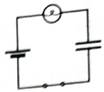
A capacitor is connected to a battery, bulb, and switch as shown. Assume that the switch has been closed for an extended period of time.
1. Predict whether the brightness of the bulb is the same as, greater than, or less than the brightness of a single bulb connected to a battery. Explain.
2. Predict how the potential difference across the battery to the potential differences across the capacitor plates and to the potential difference across the bulb. Explain.
3. Briefly describe the distribution of charge, if any, on the capacitor plates.
Recall the relationship between the charge on a capacitor and the potential difference across the capacitor. Use this relationship to describe how you could use a voltmeter to determine the charge on a capacitor.
4. Obtain the circuit and a voltmeter. Check your predictions for parts 1 and 2.
(1)
To Explain:Whether the brightness of the bulb is the same as, greater than or less than the brightness of a single bulb connected to a battery.
Answer to Problem 1aT
Brightness of the bulb changes with the time in RC circuit but it is constant in case of battery only.
Explanation of Solution
Introduction:
Ohm’s Law: The current in the circuit is directly proportional to the potential difference and the constant of proportionality is known as resistance R.
The potential difference across the capacitor is given as:
Where,
A RC circuit with a battery connected to the capacitor through a Bulb with a resistance of
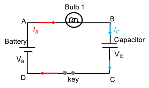
Figure 1: A RC circuit with a battery, bulb and a capacitor
After a long time, the circuit will behave as an open circuit and Therefore, current in the circuit drops to zero with the time till the capacitor voltage equals to the battery voltage.During initial moment, the brightness of the bulb in this RC is equivalent to the single bulb with the battery.But as the time passes, current starts dropping, hence, brightness decreases till the circuit becomes open due to the charging of the capacitor.
Conclusion:
Brightness of the bulb changes with the time in RC circuit but it is constant in case of battery only.
(2)
To Compare: The potential difference across capacitor, bulb and battery.
Answer to Problem 1aT
The voltage difference between the terminals of the battery is
Explanation of Solution
Introduction:
Ohm’s Law: The current in the circuit is directly proportional to the potential difference and the constant of proportionality is known as resistance R.
The potential difference across the capacitor is given as:
Where
A RC circuit with a battery connected to the capacitor through a Bulb with a resistance of

Figure 2: A RC circuit with a battery, bulb and a capacitor
The voltage difference between the terminals of the battery is
Hence, the voltage through the loop can be written as:
Conclusion:
The voltage difference between the terminals of the battery is
(3)
Charge distribution on the plates of the capacitor.
Answer to Problem 1aT
One of the plates accumulates positive and other negative charge in equal magnitude.
Explanation of Solution
Introduction:
The charge on the capacitor is directly proportional to the potential difference across the capacitor plates,
Where ‘C’ is the constant known as the capacitance which depends on the material and design property of the capacitor.
In given circuit, shown in Figure 3, the positive terminal of the battery is connected with the upper plate of the capacitor and the lower one with negative terminal of the battery.
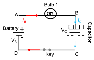
Figure 3: Charge distribution on the capacitor
Current flows from positive terminal of the battery to towards the bulb. Basically, current is in the opposite direction of the flow of the electrons. Electrons from the upper plate of the capacitor starts moving towards positive terminal of the battery and leaves the upper plate positive and electrons in the lower plate are repelled from the negative terminal of the battery. This accumulation of the charge happens till the potential difference across the plate is equal to the battery voltage. Also, the charge on the plates is equal in magnitude and opposite in charge.
Conclusion:
Hence, one of the plates of the capacitor accumulates positive and other negative charge in equal magnitude.
(4)
To Check: The predictions using voltmeter in the circuit.
Explanation of Solution
Introduction:
Ohm’s Law: The current in the circuit is directly proportional to the potential difference and the constant of proportionality is known as resistance R.
The charge on the capacitor is directly proportional to the potential difference across the capacitor plates,
Where ‘C’ is the constant known as the capacitance which depends on the material and design property of the capacitor.
In given circuit, shown in Figure 4, voltmeters are connected parallel to the battery, bulb and the capacitor in order to observe the potential for each circuit element after capacitor is fully charged. Once the capacitor is fully charged, circuit becomes open circuit and hence, no current flows through the circuit.
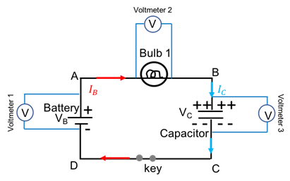
Figure 3: Circuit to calculate Vpotential across battery, bulb and the capacitor
Let say the battery has a
After a long time,the battery voltage is dropped cross the capacitor andpotential across the capacitor is calculated as 5 V and the voltmeter 3 reads 5 V.
Potential across the bulb, and the voltmeter 2 reads 0 V.
Voltmeter 1 reads 5 V.
Charge on the capacitor will be:
Conclusion:
Hence, potential across the battery and the capacitor is 5 V and the bulb is 0 V. Charge on the capacitor is
Want to see more full solutions like this?
Chapter 6 Solutions
Tutorials in Introductory Physics
Additional Science Textbook Solutions
Applied Physics (11th Edition)
Physics for Scientists and Engineers: A Strategic Approach, Vol. 1 (Chs 1-21) (4th Edition)
Life in the Universe (4th Edition)
Physics for Scientists and Engineers with Modern Physics
College Physics: A Strategic Approach (3rd Edition)
Lecture- Tutorials for Introductory Astronomy


- B. Directions: Read, understand, and perform the tasks by applying what you learned. 1. Make a Venn Diagram comparing emf of a source and potential difference across the circuit. 2. The battery supplies a maximum voltage of 12 V. When it is connected to an external circuit, the voltage measured by the voltmeter across the circuit is only 10 V. Is this possible? Explain your answer. 3. Why do the problems occur when an ammeter is connected in parallel with the lamp?arrow_forward4. If 6 coulombs of charge flow past point A in a circuit in 3 seconds, then the current at point A is a. 18 amperes b. 6 amperes c. 2 Coulombs d. 2 amperes Explain: 5. In which of the following situations will the light bulb light? Justify your answer by comparing the current flow in each case. Darrow_forwardII. Solve for the total voltage, individual voltages, total current, individual currents, total resistance, and individual resistances in each circuit diagram. Write your answers in the table provided beside each circuit diagram and show all HANDWRITTEN solutions in the last page. 1. Type of Connection: VT = 15.0 V R1 = 7.00 2 R2 = 4.00 2 R3 = 2.00 2 VI = I = RT = Vi = R1 = V2 = 12 = R2 = V3 = 13 = R3 =arrow_forward
- 1. Will the bulb light for the whole time that the capacitor discharges? Explain. 2. Say why this method (of measuring the size of an obstacle) isn’t useful.arrow_forwardFor the circuit below. Hint, use the fact that the change in voltage is equal across all branches in a parallel circuit. ΔV1=ΔV2, R1I1=R2I2 Determine I2. Determine I3. Determine I4. Determine IT.arrow_forwardThe diagram at the right shows two identical resistors - R1 and R2 - placed in a circuit with a 12-Volt battery. If a third resistor (R3), identical to the other two is added in series with the first two, then theelectric potential difference (voltage drop) across each of the three individual resistors will... A. Decrease B. Increase C. Remain the samearrow_forward
- A number of light bulbs are to be connected to a battery. a. Which will provide more overall brightness, connecting them in series or in parallel? b. Which will run the battery down faster, the bulbs connected in series or in parallel? EXPLAIN YOUR ANSWERarrow_forwardDirection. Answer each problem and show your solutions cleanly and clearly. Draw diagrams. 1. Three capacitors when connected in series gives an equivalent capacitance of 1.2 uF. When they are connected in parallel, the equivalent capacitance is 12.4 uF. The capacitance of the second capacitor is 1.5 times the first. Find the capacitance of each. Three capacitors when connected in series gives an equivalent capacitance of 1.2 uF. When they are connected in parallel, the equivalent capacitance is 12.4 uF. The capacitance of the second capacitor is 1.5 times the first. Find the capacitance of each. Answer: 4, 6, 2.4 uFarrow_forwardConsider the following circuit R1 V R2 where V = 30V, R2 = 30 and R = 30. 1. Are the resistors connected in series or parallel? 2. What is the equivalent resistance of the resistor pair. 3. Use V = IR and the equivalent resistance to find the total current though the battery. %3D 4. How much current flows through each of the two original resistors? wwarrow_forward
- 2. Charging a capacitor through a resistor. The capacitor initially starts with no charge. Refer to the circuit diagram on the right. R = 1800 2 C = 225 µF hematical ex + (e). Explain what happens to the voltage across the capacitor after the time interval t= 5 time constants. (). Carefully draw a graph of the time dependent behavior of the voltage across the capacitor, and label everything! (g). Calculate the time elapsed when the voltage across the capacitor is equal to the voltage across the Vps = 10 volts resistor.arrow_forwardA portion of a larger circuit is shown in the diagram below. The potential drop between points b and a is Vba = 4.0 V. Similarly, Vcb =3.5 V, Vcd = 2.0 V, Vdf = -0.5 V. Here, if Vba is greater than zero, then a is at a higher potential than b. Answer the following questions in SI units. 1. What is the potential difference Vgf? 2. What is the potential difference Vca? 3. What is the potential difference Vag?arrow_forward8. Consider the circuit shown on the right. Rank the brightness of the bulbs in the circuit. Use the symbols =, . Explain your ranking. B Aarrow_forward
 College PhysicsPhysicsISBN:9781305952300Author:Raymond A. Serway, Chris VuillePublisher:Cengage Learning
 University Physics (14th Edition)PhysicsISBN:9780133969290Author:Hugh D. Young, Roger A. FreedmanPublisher:PEARSON
 Introduction To Quantum MechanicsPhysicsISBN:9781107189638Author:Griffiths, David J., Schroeter, Darrell F.Publisher:Cambridge University Press
 Physics for Scientists and EngineersPhysicsISBN:9781337553278Author:Raymond A. Serway, John W. JewettPublisher:Cengage Learning
 Lecture- Tutorials for Introductory AstronomyPhysicsISBN:9780321820464Author:Edward E. Prather, Tim P. Slater, Jeff P. Adams, Gina BrissendenPublisher:Addison-Wesley
 College Physics: A Strategic Approach (4th Editio...PhysicsISBN:9780134609034Author:Randall D. Knight (Professor Emeritus), Brian Jones, Stuart FieldPublisher:PEARSON