
Videos
Set up the circuit with three bulbs as shown and observe their brightness.
Before making the voltmeter measurements, predict the ranking of the potential difference across the battery and each bulb
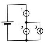
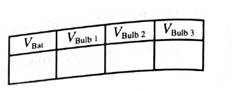
Measure the potential difference across each element in the circuit. If your measurement are not consistent with your ranking above, resolve the inconsistencies.

Learn your wayIncludes step-by-step video

Chapter 6 Solutions
Tutorials in Introductory Physics
Additional Science Textbook Solutions
University Physics with Modern Physics (14th Edition)
University Physics (14th Edition)
University Physics Volume 2
Physics: Principles with Applications
College Physics
College Physics: A Strategic Approach (4th Edition)


- What is the current read by the ammeter in the circuit below? Let R1 = 1 kiloohm, R2 = 2 kiloohm, R3 = 3 kiloohm, and the emf of the ideal source is 5 volts. Input R1, R2, and R3 for resistors R1, R2, and R3 respectively. Input E for the emf E. Use context clues to figure out if you need to input a numerical value, variable, word, etc. All numerical answers should be in three significant figures. R1 R2 R3 A First we calculate the current across each resistor. From Ohm's law, we arrive at a general formula for current: Plugging in values, the current across the resistor R1 is equal to: (Please note that the current is in milliamperes) 4 = mA Similarly the current across R2 is: And the current across R3 is: The current read by the ammeter is the sum of the currents across each resistor: 1=h+l2+l3 mA Alternatively, we can solve for the current across the ammeter by first calculating the equivalent resistance and then applying Ohm's law. The equivalent resistance of the three resistors in…arrow_forwardConsider the circuit shown in (Figure 1). Suppose that E = 10 V. Find the current through the resistor c. Find the potential difference across the resistor c. Find the current through the resistor d. Find the potential difference across the resistor d.arrow_forwardConsider the circuit shown in (Figure 1). Assume E = 12 V. What is the equivalent capacitance? What is the charge on 3.0 μF capacitor? What is the charge on 4.0 μF capacitor? What is the charge on 6.0 μF capacitor?arrow_forward
- Consider the circuit shown in the figure. Suppose the four resistors in this circuit have the values R1= 13 Ω, R2= 6.1 Ω, R3= 8.0 Ω, and R4 = 10 Ω, and that the emf of the battery is E= 15 V A) Find the current through each resistor using the rules for series and parallel resistors. Express your answers using two significant figures separated by commas. B) Find the current through each resistor using Kirchhoff's rules. Express your answers using two significant figures separated by commas.arrow_forwardWhat is the current read by the ammeter in the circuit below? Let R1 = 1 kiloohm, R2 = 2 kiloohm, R3 = 3 kiloohm, and the emf of the ideal source is 5 volts. Input R1, R2, and R3 for resistors R1, R2, and R3 respectively. Input E for the emf €. Use context clues to figure out if you need to input a numerical value, variable, word, etc. All numerical answers should be in three significant figures. %3D R1 R2 R3 (A First we calculate the current across each resistor. From Ohm's law, we arrive at a general formula for current:arrow_forwardIn the circuit below, if the battery in the circuit below is 3V, resistor R1=2772, and resistor R2=4122, what is the total or net current in the circuit units of mA? High potential I R1 R2 + 12 I Low potential Note: It is understood that the unit of your answer is in milli-Amps (mA), however do not explicitly include units in your answer. Enter only a number. If you do enter a unit, your answer will be counted wrong.arrow_forward
- What is the current read by the ammeter in the circuit below? Let R1 = 1 kiloohm, R2 = 2 kiloohm, R3 = 3 kiloohm, and the emf of the ideal source is 5 volts. Input R1, R2, and R3 for resistors R1, R2, and R3 respectively. Input E for the emf E: Use context clues to figure out if you need to input a numerical value, variable, word, etc. All numerical answers should be in three significant figures. R1 R2 R3arrow_forwardPROBLEMS: Find the V across, I through, and P used by each resistor in the following simple circuit. Show your work. Be sure to include units in your answers. R1 50 V R1 R3 10 Q R2 V- 30 V R2 16 0 R3 R4 R4 R5 20 R5arrow_forwardPhysics written by hand. Determine the circuit's behavior for each of the following cases after S is again closed: i) The circuit element connecting alpha to beta is an ideal voltmeter. Also what would the voltmeter measure. ii) The circuit element connecting alpha to beta is an ideal ammeter. Also what does this ammeter measure.arrow_forward
- Find the total capacitance of the combination of capacitors shown: 5.0 uF 3.5 μF 8.0 uF I 1.5 μF H 0.75 μF 15 μF J Hint: Identify parts of the circuit that are parallel or in series. Replace these parts by their equivalent capacitance. Draw a circuit diagram of the simplified circuit with the equivalent capacitances. Repeat the steps above until you simiplfy the circuit as much as possible. C = HFarrow_forwardState which of the following statements are true and which are false. Give reasons for your answers. a) A very simple circuit consists of a battery connected across a resistor. In this circuit, the battery and the resistor are both in series and also in parallel. b) A resistor R and a capacitor C connected in series combine as = + 1 1 RC R c) Natural uranium is not radioactive until it has been processed by enrichment for use in fission reactors or bombs. d) Infrared light is more likely to cause electrons to be emitted from a metal than ultraviolet light. e) Special and General Relativity effects both matter for the operation of GPS, the former slow- ing down the clocks on GPS satellites relative to clocks on Earth and the latter speeding them up.arrow_forward1. What is the time constant of the circuit formed when a and c are connected? Give your answer in ms to 3 significant digits. 2. What is the time constant of the circuit formed when b and c connected? Give your answer in ms to 3 significant digits. 3. You perform the following sequence of events. The capacitor starts uncharged and the switch is flipped to connect a and c. The capacitor is charged for 20 ms. The switch is then flipped to connect b and c, and the capacitor is discharged for 26 ms, at which time the switch is set to the position where it is not in contact with either a or b. What is the voltage on the capacitor? Give your answer to 2 significant digits.arrow_forward
 College PhysicsPhysicsISBN:9781305952300Author:Raymond A. Serway, Chris VuillePublisher:Cengage Learning
 University Physics (14th Edition)PhysicsISBN:9780133969290Author:Hugh D. Young, Roger A. FreedmanPublisher:PEARSON
 Introduction To Quantum MechanicsPhysicsISBN:9781107189638Author:Griffiths, David J., Schroeter, Darrell F.Publisher:Cambridge University Press
 Physics for Scientists and EngineersPhysicsISBN:9781337553278Author:Raymond A. Serway, John W. JewettPublisher:Cengage Learning
 Lecture- Tutorials for Introductory AstronomyPhysicsISBN:9780321820464Author:Edward E. Prather, Tim P. Slater, Jeff P. Adams, Gina BrissendenPublisher:Addison-Wesley
 College Physics: A Strategic Approach (4th Editio...PhysicsISBN:9780134609034Author:Randall D. Knight (Professor Emeritus), Brian Jones, Stuart FieldPublisher:PEARSON