
Shigley's Mechanical Engineering Design (McGraw-Hill Series in Mechanical Engineering)
10th Edition
ISBN: 9780073398204
Author: Richard G Budynas, Keith J Nisbett
Publisher: McGraw-Hill Education
expand_more
expand_more
format_list_bulleted
Concept explainers
Videos
Textbook Question
Chapter 5, Problem 63P
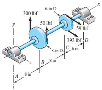
The figure shows a shaft mounted in bearings at A and D and having pulleys at B and C. The forces shown acting on the pulley surfaces represent the belt tensions. The shaft is to be made of AISI 1035 CD steel. Using a conservative failure theory with a design factor of 2, determine the minimum shaft diameter to avoid yielding.
Problem 5–63
Expert Solution & Answer
Want to see the full answer?
Check out a sample textbook solution
Students have asked these similar questions
a) The rotating step shaft is subjected to the force as shown in the figure. It is supported by bearings at A and F. The shaft is machined using AISI 1040 CD steel. Determine the minimum fatigue
factor of safety based on achieving infinite life. If infinite life is not predicted, estimate the number of cycles
failure. Also check for yielding.
Given Data: (Notch sensitivity (q)=0.8, Sut=85 kpsi, Syield= 71 kpsi, Surface condition modification factor ka=0.879, Size modification factor kb=0.790, Load modification factor kc=1, fatigue fraction
(f)=0.867)
* In order to determine Kt; Use Figure A-15-9 in your textbook.
Dimensions are in inch and all fillet radius:1/14 inch
y
860 lbf
de
1.75
1.5
1.0
1.0
B
V A|
D
E
F
0.5
8
-8.5-
R1
R2
-19.5
20
5-63
The figure shows a shaft mounted in bearings at A and D and having pulleys at B and C. The
forces shown acting on the pulley surfaces represent the belt tensions. The shaft is to be made of
AISI 1035 CD steel. Using a conservative failure theory with a design factor of 2, determine the
minimum shaft diameter to avoid yielding.
f-in R
300 Ibf
50 lbf
59 Ibf
392 lbf D
Problem 5-63
C 6 in
8-in D.
8 in
B
8 in
The figure shows a shaft mounted in bearings at A and D and having pulleys at B and C. The forces shown acting on the pulley surfaces represent the belt tensions. The shaft is to be made of AISI 1035 CD steel. The shaft is rotating at speed of 1000 rpm. Find the minimum factor of safety for fatigue based on infinite life. If the life is not infinite, estimate the number of cycles. Be sure to check for yielding. Take shaft diameter to be 1.5 inches.
Chapter 5 Solutions
Shigley's Mechanical Engineering Design (McGraw-Hill Series in Mechanical Engineering)
Ch. 5 - A ductile hot-rolled steel bar has a minimum yield...Ch. 5 - A ductile hot-rolled steel bar has a minimum yield...Ch. 5 - A ductile hot-rolled steel bar has a minimum yield...Ch. 5 - A ductile hot-rolled steel bar has a minimum yield...Ch. 5 - A ductile hot-rolled steel bar has a minimum yield...Ch. 5 - Prob. 6PCh. 5 - 5-7 to 5-11 An AISI 1018 steel has a yield...Ch. 5 - 5-7 to 5-11 An AISI 1018 steel has a yield...Ch. 5 - 5-7 to 5-11 An AISI 1018 steel has a yield...Ch. 5 - 5-7 to 5-11 An AISI 1018 steel has a yield...
Ch. 5 - 5-7 to 5-11 An AISI 1018 steel has a yield...Ch. 5 - A ductile material has the properties Syt = 60...Ch. 5 - Prob. 13PCh. 5 - Prob. 14PCh. 5 - Prob. 15PCh. 5 - 5-14 to 5-18 An AISI 4142 steel QT at 800F...Ch. 5 - 5-14 to 5-18 An AISI 4142 steel QT at 800F...Ch. 5 - 5-14 to 5-18 An AISI 4142 steel QT at 800F...Ch. 5 - A brittle material has the properties Sut = 30...Ch. 5 - Repeat Prob. 519 by first plotting the failure...Ch. 5 - For an ASTM 30 cast iron, (a) find the factors of...Ch. 5 - For an ASTM 30 cast iron, (a) find the factors of...Ch. 5 - Prob. 23PCh. 5 - For an ASTM 30 cast iron, (a) find the factors of...Ch. 5 - 5-21 to 5-25 For an ASTM 30 cast iron, (a) find...Ch. 5 - 5-26 to 5-30 A cast aluminum 195-T6 exhibits Sut =...Ch. 5 - 5-26 to 5-30 A cast aluminum 195-T6 exhibits Sut =...Ch. 5 - 5-26 to 5-30 A cast aluminum 195-T6 exhibits Sut =...Ch. 5 - 5-26 to 5-30 A cast aluminum 195-T6 exhibits Sut =...Ch. 5 - 5-26 to 5-30 A cast aluminum 195-T6 exhibits Sut =...Ch. 5 - 5-31 to 5-35 Repeat Probs. 526 to 530 using the...Ch. 5 - 5-31 to 5-35 Repeat Probs. 526 to 530 using the...Ch. 5 - Repeat Probs. 526 to 530 using the modified-Mohr...Ch. 5 - Repeat Probs. 526 to 530 using the modified-Mohr...Ch. 5 - Repeat Probs. 526 to 530 using the modified-Mohr...Ch. 5 - This problem illustrates that the factor of safety...Ch. 5 - For the beam in Prob. 344, p. 147, determine the...Ch. 5 - A 1020 CD steel shaft is to transmit 20 hp while...Ch. 5 - For the problem specified in the table, build upon...Ch. 5 - For the problem specified in the table, build upon...Ch. 5 - 5-39 to 5-55 For the problem specified in the...Ch. 5 - Prob. 42PCh. 5 - For the problem specified in the table, build upon...Ch. 5 - For the problem specified in the table, build upon...Ch. 5 - Prob. 45PCh. 5 - 5-39 to 5-55 For the problem specified in the...Ch. 5 - Prob. 47PCh. 5 - For the problem specified in the table, build upon...Ch. 5 - For the problem specified in the table, build upon...Ch. 5 - For the problem specified in the table, build upon...Ch. 5 - For the problem specified in the table, build upon...Ch. 5 - 5-39 to 5-55 For the problem specified in the...Ch. 5 - 5-39 to 5-55 For the problem specified in the...Ch. 5 - For the problem specified in the table, build upon...Ch. 5 - For the problem specified in the table, build upon...Ch. 5 - Build upon the results of Probs. 384 and 387 to...Ch. 5 - Using F = 416 lbf, design the lever arm CD of Fig....Ch. 5 - A spherical pressure vessel is formed of 16-gauge...Ch. 5 - This problem illustrates that the strength of a...Ch. 5 - Prob. 60PCh. 5 - A cold-drawn AISI 1015 steel tube is 300 mm OD by...Ch. 5 - Prob. 62PCh. 5 - The figure shows a shaft mounted in bearings at A...Ch. 5 - By modern standards, the shaft design of Prob. 563...Ch. 5 - Build upon the results of Prob. 340, p. 146, to...Ch. 5 - For the clevis pin of Prob. 340, p. 146, redesign...Ch. 5 - A split-ring clamp-type shaft collar is shown in...Ch. 5 - Prob. 68PCh. 5 - Prob. 69PCh. 5 - Prob. 70PCh. 5 - Two steel tubes have the specifications: Inner...Ch. 5 - Repeal Prob. 5-71 for maximum shrink-fit...Ch. 5 - Prob. 73PCh. 5 - Two steel lubes are shrink-filled together where...Ch. 5 - Prob. 75PCh. 5 - Prob. 76PCh. 5 - Prob. 77PCh. 5 - Prob. 78PCh. 5 - Prob. 79PCh. 5 - Prob. 80PCh. 5 - Prob. 81PCh. 5 - For Eqs. (5-36) show that the principal stresses...Ch. 5 - Prob. 83PCh. 5 - A plate 100 mm wide, 200 mm long, and 12 mm thick...Ch. 5 - A cylinder subjected to internal pressure pi has...
Knowledge Booster


Learn more about
Need a deep-dive on the concept behind this application? Look no further. Learn more about this topic, mechanical-engineering and related others by exploring similar questions and additional content below.Similar questions
- Repeat Problem 10.3-15 using L = 3.5 m, max = 3 mm, and EI = 800 kN·m2.arrow_forwardA crank arm consists of a solid segment of length bxand diameter rf, a segment of length bltand a segment of length byas shown in the figure. Two loads P act as shown: one parallel to — vand another parallel to —y. Each load P equals 1.2 kN. The crankshaft dimensions are A] = 75 mm, fr> = 125 mm, and b3= 35 mm. The diameter of the upper shaft isd = 22 mm, (a) Determine the maximum tensile, compressive, and shear stresses at point A, which is located on the surface of the shaft at the z axis. (b) Determine the maximum tensile, compressive, and shear stresses at point B, which is located on the surface of the shaft at the y axisarrow_forwardRepeat Problem 11.2-3 assuming that R= 10 kN · m/rad and L = 2 m.arrow_forward
- What is the maximum power that can be delivered by a hollow propeller shaft (outside diameter 50 mm, inside diameter 40 mm, and shear modulus of elasticity 80 GPa) turning at 600 rpm if the allowable shear stress is 100 MPa and the allowable rate of twist is 3.0°/m?arrow_forwardA gear reduction unit uses the countershaft shown in the figure. Gear A receives power from another gear with the transmitted force FA applied at the 20 pressure angle as shown. The power is transmitted through the shaft and delivered through gear B through a transmitted force Fg at the pressure angle shown. For the steel countershaft shown below, assume the bearings have a maximum slope specification of 0.064" for good bearing life. Does the dia shown below meet the requirement? if not determine a suitable shaft diameter. 1.25-in da Gear A F₁-300- Gear B Sindia The minimum shaft diameter is in.arrow_forwardThe rotating shaft shown in the figure is machined from AISI 1020 CD steel. It is subjected to a force of F = 6 kN. Find the minimum factor of safety for fatigue based on infinite life. If the life is not infinite, estimate the number of cycles. Be sure to check for yielding. The diameter of the bar is 35 mm and the radius of the step down in the shaft is 3 mm. All dimensions listed below are in mm. 25 D. 20 - 20 -35 D. 180 -3 R. 500- F 280- -175- -50 D. -25 D. -20 20arrow_forward
- 6-10 A rotating shaft of 25-mm diameter is simply supported by bearing reaction forces R, and R2. The shaft is loaded with a transverse load of 13 kN as shown in the figure. The shaft is made from AISI 1045 hot-rolled steel. The surface has been machined. Determine (a) the minimum static factor of safety based on yielding. (b) the endurance limit, adjusted as necessary with Marin factors. (c) the minimum fatigue factor of safety based on achieving infinite life. (d) If the fatigue factor of safety is less than 1 (hint: it should be for this problem), then estimate the life of the part in number of rotations.arrow_forwardA gear reduction unit uses the countershaft shown in the figure. Gear A receives power from another gear with the transmitted force FA applied at the 20° pressure angle as shown. The power is transmitted through the shaft and delivered through gear B through a transmitted force Fg at the pressure angle shown. For the steel countershaft shown below, assume the bearings have a maximum slope specification of 0.062° for good bearing life. Check wether the shaft dia below meets the requirement. If not determine a suitable shaft diameter. 400 mm FB 350 mm 25° 300 mm FA = 11 kN• 20° 50-mm dia. Gear A, 600-mm dia. Gear B, 300-mm dia. mm. The minimum shaft diameter is determined to bearrow_forwardQ1 (b): A cold-drawn solid steel shaft is driven at N=287 RPM carries two gears D andE, as shown in the figure. Gear D has an input power of Pp= 9 kW, while gear E gives an equal output power. For a factor of safety of n=2.5, design the shaft according to the following failure criteria: Assume Sy 309 MPa, Sut= 598 MPa, K=1.4, Ks =1.4 15 kg 15 kg D 0.4 m e 0.6 m 0.4 m - Calculate the mean torque, Tm in N.m units upto 4 digits after decimal. Enter only numeric value without units. Assume k = 0.81 and the shaft is operating at room temperature of 70°F with 50% reliability.arrow_forward
- Figure below shows a portion of a pump that is gear-driven at uniform load and speed. The 25 mm diameter solod shaft supported by the bearings is to be made of machined AISI 1045 CD steel. The helical gear is subjected to the axial force F =499 y a radial load F = 741 N and a tangential load of F=2,006 N. Assume the component is operating at room temperature of 70°F and the material has 50% reliability factor. 25-mm solid Bending K, = 2.0 round shaft Fillet Torsional K = 1.5 F. F, Axial K, = 1.8 F Pump Helical spur gear 50 mm -250-mm dia.- FIGURE 1. Identify the critical location(s) of stress and show it clearly in a diagram. 2. Identify cleary, all the components of stresses (at the critical point) that will be calculated (by drawing and clearly showing the XYZ axes) and show it in a matrix form. Show which components of stresses will have a value zero or non-zero. 3. Calculate the principal stresses and principal directions. Show the principal stresses clearly in a stress element…arrow_forwardQ1 (a): A cold-drawn solid steel shaft is driven at N=295 RPM carries two gears D and E, as shown in the figure. Gear D has an input power of Pp= 11 kW, while gear E gives an equal output power. For a factor of safety of n=2.2, design the shaft according to the following failure criteria: Assume Sy= 291 MPa, Sut= 597 MPa, Kf=1.3, K=1.4 15 kg 15 kg A E 0.4 m e 0.6 m 0.4 m Calculate endurance limit, Se, in MPa units assuming all the Marin factors are unity. Enter only numeric value without units. Assume k=0.77 and the shaft is operating at room temperature of 70°F with 50% reliability.arrow_forwardThe figure below shows a boat propeller mounted on a drive shaft with a 7 mm diameter (d) cylindrical drive pin inserted through the hub and the shaft. The drive shaft diameter, D, inside the hub is 69 mm. The pin is made from AISI 1020 cold rolled steel, which has a yield stress of 427 MPa and an ultimate stress of 621 MPa. If the drive pin is subjected to an overload (e.g. strikes a log), calculate the torque (Nm) required to shear the pin. Note: Assume that the max shear stress of the pin material is approximately equal 82% of the ultimate tensile stress. Do not include units in your answer. Pin F Hub Drive pin Shaft Drive shaft F Shear planes Hub Answer:arrow_forward
arrow_back_ios
SEE MORE QUESTIONS
arrow_forward_ios
Recommended textbooks for you
 Mechanics of Materials (MindTap Course List)Mechanical EngineeringISBN:9781337093347Author:Barry J. Goodno, James M. GerePublisher:Cengage Learning
Mechanics of Materials (MindTap Course List)
Mechanical Engineering
ISBN:9781337093347
Author:Barry J. Goodno, James M. Gere
Publisher:Cengage Learning
Everything About COMBINED LOADING in 10 Minutes! Mechanics of Materials; Author: Less Boring Lectures;https://www.youtube.com/watch?v=N-PlI900hSg;License: Standard youtube license