
Shigley's Mechanical Engineering Design (McGraw-Hill Series in Mechanical Engineering)
10th Edition
ISBN: 9780073398204
Author: Richard G Budynas, Keith J Nisbett
Publisher: McGraw-Hill Education
expand_more
expand_more
format_list_bulleted
Concept explainers
Videos
Textbook Question
Chapter 5, Problem 36P
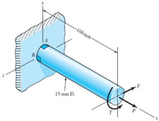
This problem illustrates that the factor of safety for a machine element depends on the particular point selected for analysis. Here you are to compute factors of safety, based upon the distortion-energy theory, for stress elements at A and B of the member shown in the figure. This bar is made of AISI 1006 cold-drawn steel and is loaded by the forces F = 0.55 kN, P = 4.0 kN, and T = 25 N · m.
Problem 5–36
Expert Solution & Answer
Want to see the full answer?
Check out a sample textbook solution
Chapter 5 Solutions
Shigley's Mechanical Engineering Design (McGraw-Hill Series in Mechanical Engineering)
Ch. 5 - A ductile hot-rolled steel bar has a minimum yield...Ch. 5 - A ductile hot-rolled steel bar has a minimum yield...Ch. 5 - A ductile hot-rolled steel bar has a minimum yield...Ch. 5 - A ductile hot-rolled steel bar has a minimum yield...Ch. 5 - A ductile hot-rolled steel bar has a minimum yield...Ch. 5 - Prob. 6PCh. 5 - 5-7 to 5-11 An AISI 1018 steel has a yield...Ch. 5 - 5-7 to 5-11 An AISI 1018 steel has a yield...Ch. 5 - 5-7 to 5-11 An AISI 1018 steel has a yield...Ch. 5 - 5-7 to 5-11 An AISI 1018 steel has a yield...
Ch. 5 - 5-7 to 5-11 An AISI 1018 steel has a yield...Ch. 5 - A ductile material has the properties Syt = 60...Ch. 5 - Prob. 13PCh. 5 - Prob. 14PCh. 5 - Prob. 15PCh. 5 - 5-14 to 5-18 An AISI 4142 steel QT at 800F...Ch. 5 - 5-14 to 5-18 An AISI 4142 steel QT at 800F...Ch. 5 - 5-14 to 5-18 An AISI 4142 steel QT at 800F...Ch. 5 - A brittle material has the properties Sut = 30...Ch. 5 - Repeat Prob. 519 by first plotting the failure...Ch. 5 - For an ASTM 30 cast iron, (a) find the factors of...Ch. 5 - For an ASTM 30 cast iron, (a) find the factors of...Ch. 5 - Prob. 23PCh. 5 - For an ASTM 30 cast iron, (a) find the factors of...Ch. 5 - 5-21 to 5-25 For an ASTM 30 cast iron, (a) find...Ch. 5 - 5-26 to 5-30 A cast aluminum 195-T6 exhibits Sut =...Ch. 5 - 5-26 to 5-30 A cast aluminum 195-T6 exhibits Sut =...Ch. 5 - 5-26 to 5-30 A cast aluminum 195-T6 exhibits Sut =...Ch. 5 - 5-26 to 5-30 A cast aluminum 195-T6 exhibits Sut =...Ch. 5 - 5-26 to 5-30 A cast aluminum 195-T6 exhibits Sut =...Ch. 5 - 5-31 to 5-35 Repeat Probs. 526 to 530 using the...Ch. 5 - 5-31 to 5-35 Repeat Probs. 526 to 530 using the...Ch. 5 - Repeat Probs. 526 to 530 using the modified-Mohr...Ch. 5 - Repeat Probs. 526 to 530 using the modified-Mohr...Ch. 5 - Repeat Probs. 526 to 530 using the modified-Mohr...Ch. 5 - This problem illustrates that the factor of safety...Ch. 5 - For the beam in Prob. 344, p. 147, determine the...Ch. 5 - A 1020 CD steel shaft is to transmit 20 hp while...Ch. 5 - For the problem specified in the table, build upon...Ch. 5 - For the problem specified in the table, build upon...Ch. 5 - 5-39 to 5-55 For the problem specified in the...Ch. 5 - Prob. 42PCh. 5 - For the problem specified in the table, build upon...Ch. 5 - For the problem specified in the table, build upon...Ch. 5 - Prob. 45PCh. 5 - 5-39 to 5-55 For the problem specified in the...Ch. 5 - Prob. 47PCh. 5 - For the problem specified in the table, build upon...Ch. 5 - For the problem specified in the table, build upon...Ch. 5 - For the problem specified in the table, build upon...Ch. 5 - For the problem specified in the table, build upon...Ch. 5 - 5-39 to 5-55 For the problem specified in the...Ch. 5 - 5-39 to 5-55 For the problem specified in the...Ch. 5 - For the problem specified in the table, build upon...Ch. 5 - For the problem specified in the table, build upon...Ch. 5 - Build upon the results of Probs. 384 and 387 to...Ch. 5 - Using F = 416 lbf, design the lever arm CD of Fig....Ch. 5 - A spherical pressure vessel is formed of 16-gauge...Ch. 5 - This problem illustrates that the strength of a...Ch. 5 - Prob. 60PCh. 5 - A cold-drawn AISI 1015 steel tube is 300 mm OD by...Ch. 5 - Prob. 62PCh. 5 - The figure shows a shaft mounted in bearings at A...Ch. 5 - By modern standards, the shaft design of Prob. 563...Ch. 5 - Build upon the results of Prob. 340, p. 146, to...Ch. 5 - For the clevis pin of Prob. 340, p. 146, redesign...Ch. 5 - A split-ring clamp-type shaft collar is shown in...Ch. 5 - Prob. 68PCh. 5 - Prob. 69PCh. 5 - Prob. 70PCh. 5 - Two steel tubes have the specifications: Inner...Ch. 5 - Repeal Prob. 5-71 for maximum shrink-fit...Ch. 5 - Prob. 73PCh. 5 - Two steel lubes are shrink-filled together where...Ch. 5 - Prob. 75PCh. 5 - Prob. 76PCh. 5 - Prob. 77PCh. 5 - Prob. 78PCh. 5 - Prob. 79PCh. 5 - Prob. 80PCh. 5 - Prob. 81PCh. 5 - For Eqs. (5-36) show that the principal stresses...Ch. 5 - Prob. 83PCh. 5 - A plate 100 mm wide, 200 mm long, and 12 mm thick...Ch. 5 - A cylinder subjected to internal pressure pi has...
Knowledge Booster


Learn more about
Need a deep-dive on the concept behind this application? Look no further. Learn more about this topic, mechanical-engineering and related others by exploring similar questions and additional content below.Similar questions
- What is the maximum possible value of the clamping Force C in the jaws of the pliers shown in the figure if the ultimate shear stress in the 5-mm diameter pin is 340 MPa? What is the maximum permissible value of the applied load P to maintain a factor of safety of 3.0 with respect to failure of the pin?arrow_forwardCompare the angle of twist 1 for a thin-walled circular tube (see figure) calculated from the approximate theory for thin-walled bars with the angle of twist 2 calculated from the exact theory of torsion for circular bars, Express the ratio 12terms of the non-dimensional ratio ß = r/t. Calculate the ratio of angles of twist for ß = 5, 10, and 20. What conclusion about the accuracy of the approximate theory do you draw from these results?arrow_forwardAn aluminum bar has length L = 6 ft and diameter d = 1.375 in. The stress-strain curse for the aluminum is shown in Fig. 1.34. The initial straight, line part of the curve has a slope (modulus of elasticity) of 10.6 × 10⁶ psi. The bar is loaded by tensile forces P = 44.6 k and then unloaded. (a) That is the permanent set of the bar? (b) If the bar is reloaded. what is the proportional limit? hint: Use the concepts illustrated in Figs. l.39b and 1.40.arrow_forward
- Solve the preceding problem if the thickness of the steel plate is. t = 12 mm. the gage readings are x = 530 × 10-6 (elongation) and y = -210 -× l0-6 (shortening), the modulus is E = 200 GPa, and Poisson’s ratio is v = 0.30.arrow_forwardA crank arm consists of a solid segment of length bxand diameter rf, a segment of length bltand a segment of length byas shown in the figure. Two loads P act as shown: one parallel to — vand another parallel to —y. Each load P equals 1.2 kN. The crankshaft dimensions are A] = 75 mm, fr> = 125 mm, and b3= 35 mm. The diameter of the upper shaft isd = 22 mm, (a) Determine the maximum tensile, compressive, and shear stresses at point A, which is located on the surface of the shaft at the z axis. (b) Determine the maximum tensile, compressive, and shear stresses at point B, which is located on the surface of the shaft at the y axisarrow_forwardA steel punch consists of two shafts: upper shaft and lower shaft. Assume that the upper shaft has a diameter d1= 24 mm and the bottom shaft has a diameter d2= 16 mm. The punch is used to insert a hole in a 4 mm plate, as shown in the figure. If a force P - 70 kN is required to create the hole, what is the average shear stress in the plate and the average compressive stress in the upper and lower shaft of the punch?arrow_forward
- Repeat Problem 2.3-4, but now include the weight of the bar. Sec Table 1.1 in Appendix I for the weight density of steel.arrow_forwardThe piston in an engine is attached to a connecting rod AB, which in turn is connected to a crank arm BC (see figure). The piston slides without friction in a cylinder and is subjected to a force P (assumed to be constant) while moving to the right in the Figure. The connecting rod. with diameter d and length L, is attached at both ends by pins. The crank arm rotates about the axle at C with the pin at B moving in a circle of radius R. The axle at C, which is supported by bearings, exerts a resisting moment M against the crank arm. (a) Obtain a formula for the maximum permissible force Pallow. based upon an allowable compressive stress acin the connecting rod. (b) Calculate the Force Pallowfor the following data:arrow_forwardThe composite shaft shown in the figure is manufactured by shrink-Fitting a steel sleeve over a brass core so that the two parts act as a single solid bar in torsion. The outer diameters of the two parts are dY= 40 mm for the brass core and d2= 50 mm for the steel sleeve. The shear moduli of elasticity are Gb= 36 GPa for the brass and Gs= 80 GPa for the steel. (a) Assuming that the allowable shear stresses in the brass and steel are rb= 48 MPa and ts= 80 MPa, respectively, determine the maximum permissible torque Tmax that may be applied to the shaft. (b) If the applied torque T = 2500 kN · m, find the required diameter d2so that allowable shear stress t3is reached in the steel.arrow_forward
- Two sections of steel drill pipe, joined by bolted flange plates at Ä are being tested to assess the adequacy of both the pipes. In the test, the pipe structure is fixed at A, a concentrated torque of 500 kN - m is applied at x = 0.5 m, and uniformly distributed torque intensity t1= 250 kN m/m is applied on pipe BC. Both pipes have the same inner diameter = 200 mm. Pipe AB has thickness tAB=15 mm, while pipe BC has thickness TBC= 12 mm. Find the maximum shear stress and maximum twist of the pipe and their locations along the pipe. Assume G = 75 GPa.arrow_forwardThe strength-to-weight ratio of a structural material is defined as its load-carrying capacity divided by its weight. For materials in tension, use a characteristic tensile stress obtained from a stress-strain curve as a measure of strength. For instance, either the yield stress or the ultimate stress could be used, depending upon the particular application. Thus, the strength-to-weight ratio RS/Wfor a material in tension is defined as Rs/w= in which a is the characteristic stress and 7 is the weight density. Note that the ratio has units of length. Using the ultimate stress Uas the strength parameter, calculate the strength-to-weight ratio (in units of meters) for each of the following materials: aluminum alloy 606I-T6, Douglas fir (in bending}, nylon. structural steel ASTM-A57.2, and a titanium alloy. Obtain the material properties from Tables [-1 and 1-3 of Appendix I. When a range of values is given in a table, use the average value.arrow_forwardA shock mount constructed as shown iu the figure is used to support a delicate instrument. The mount consists of an outer steel tube with inside diameter b. a central steel bar of diameter d that supports the load P, and a hollow rubber cylinder (height /r) bonded to the tube and bar (a) Obtain a formula Tor the shear stress t in the rubber at a radial distance r from the center of the shock mount. (b) Obtain a formula Tor the downward displacement S of the central bar due to the load P. assuming that G is the shear modulus of elasticity of the rubber and that the steel tube and bar are rigid.arrow_forward
arrow_back_ios
SEE MORE QUESTIONS
arrow_forward_ios
Recommended textbooks for you
 Mechanics of Materials (MindTap Course List)Mechanical EngineeringISBN:9781337093347Author:Barry J. Goodno, James M. GerePublisher:Cengage Learning
Mechanics of Materials (MindTap Course List)
Mechanical Engineering
ISBN:9781337093347
Author:Barry J. Goodno, James M. Gere
Publisher:Cengage Learning
Hand Tools; Author: UCI Media;https://www.youtube.com/watch?v=4o0tqF0jDdo;License: Standard Youtube License