
Concept explainers
Videos
(a) Obtain a value for the Thévenin equivalent resistance seen looking into the open terminals of the circuit in Fig. 5.76 by first finding Voc and Isc. (b) Connect a 1 A test source to the open terminals of the original circuit after shorting the voltage source, and use this to obtain RTH. (c) Connect a 1 V test source to the open terminals of the original circuit after again zeroing the 2 V source, and use this now to obtain RTH.
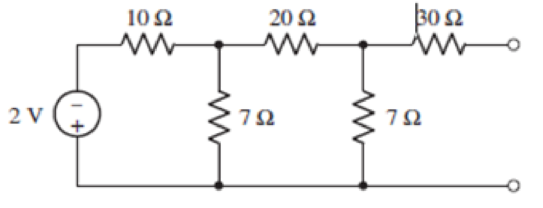
FIGURE 5.76
(a)
Find the value for the Thevenin’s equivalent resistance seen looking into the open terminals of the circuit by first finding
Answer to Problem 35E
The Thevenin’s equivalent resistance is
Explanation of Solution
Calculation:
The redrawn circuit diagram is given in Figure 1.
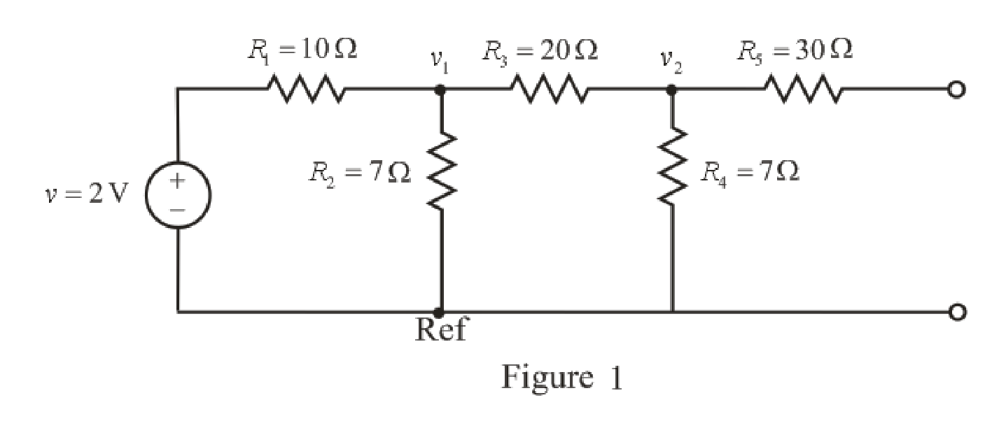
Apply KCL ay node 1,
Here,
Substitute
Rearrange for
Apply KCL at node 2,
Here,
Substitute
Rearrange for
Substitute
Rearrange for
Substitute
So, the voltage
The redrawn circuit diagram is given in Figure 2,
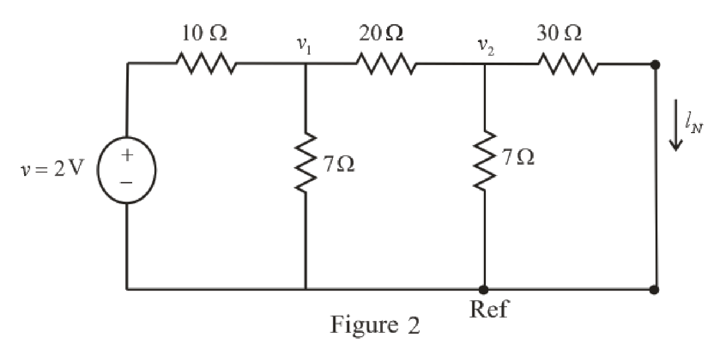
Refer to the redrawn Figure 2,
Apply KCL at node 1,
Substitute
Rearrange for
Apply KCL at node 2,
Here,
Substitute
Rearrange for
Substitute
The expression for the current flowing through
Here,
Substitute
So, the current
The expression for the Thevenin’s equivalent resistance is as follows,
Here,
Substitute
Conclusion:
Thus, the Thevenin’s equivalent resistance is
(b)
Connect a
Answer to Problem 35E
The Thevenin’s equivalent resistance is
Explanation of Solution
Calculation:
The redrawn circuit diagram is given in Figure 3,
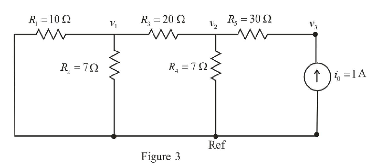
Refer to the redrawn Figure 3,
Apply KCL ay node 1,
Here,
Substitute
Rearrange for
Apply KCL at node 2,
Here,
Substitute
Rearrange for
The expression for the current flowing through
Here,
Substitute 1 A for
Rearrange for
Substitute
Substitute
Rearrange for
Substitute
The expression for the Thevenin’s equivalent resistance is as follows,
Here,
Substitute 35.43 V for
Conclusion:
Thus, the Thevenin’s equivalent resistance is
(c)
Connect a 1 V test source to the open terminals of the original circuit after again
zeroing the 2 V source, and use this now to obtain
Answer to Problem 35E
The Thevenin’s equivalent resistance is
Explanation of Solution
Calculation:
The redrawn circuit diagram is given in Figure 4,
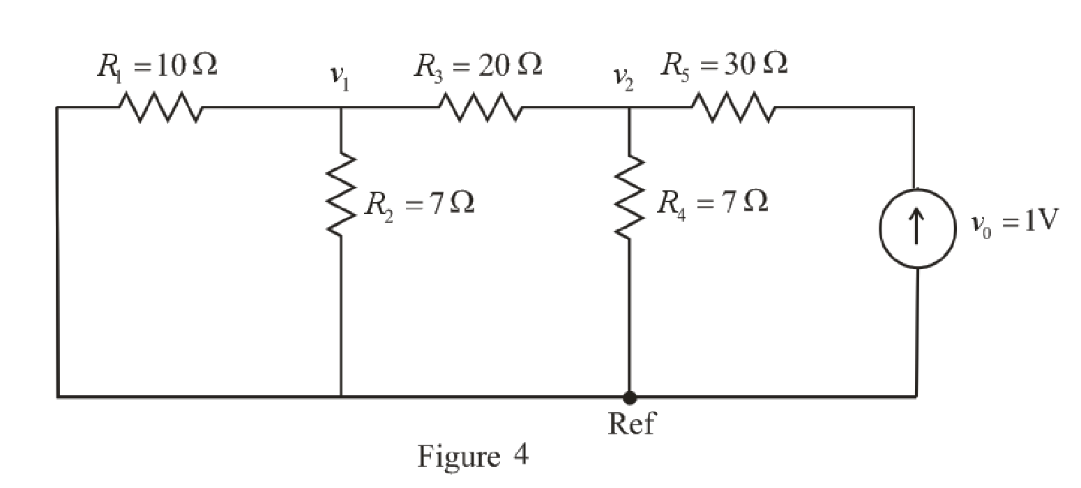
Refer to the redrawn Figure 4,
Apply KCL ay node 1,
Here,
Substitute
Rearrange for
Apply KCL at node 2,
Here,
Substitute
Rearrange for
Substitute
The expression for the Thevenin’s equivalent resistance is as follows,
Here,
Substitute 0.1532 V for
Conclusion:
Thus, the Thevenin’s equivalent resistance is
Want to see more full solutions like this?
Chapter 5 Solutions
Loose Leaf for Engineering Circuit Analysis Format: Loose-leaf


- In a two-terminal network, the open-circuit voltage measured at the given terminals by an electronic voltmeter is 100 V. A short-circuit current measured at the same terminals by an ammeter of negligible resistance is 5A. If a load resistor of 8092 is connected at the same terminals, then the current in the load resistance will bearrow_forwardAnswer All Questions: QI:A: Design a multi-range ammeter of 0.5 and 1 Amp. using a PMMC(galvanometer) of 500 internal resistance and full-scale current of 1 ma. Show the way of connection with the load Ri- B: What are the things that must be taken into consideration practically when using the ammeter. Q2: Design series ohmmeter using PMMC of 1000 internal resistance and 0.4ma full-scale deflection current. The required half-scale deflection is equal to 9kla Juse a battery of 9v]. Sketch the internal circuit diagram of the ohmmeter. Sketch also roughly the scale of the designed meter.arrow_forwardA power suppply having 220 V AC input and two fixed outputs as 10 V DC and 20 V DC is requested from you. For this purpose, a transformer with 220 V AC input / 15 V AC output, some capacitors, some silicon diodes, and zener diodes are presented. a) Design your power supply and point out DC voltage outputs b) Explain the operation of the network and all the components used in the design c) Calculate and plot input and output signals of the network Hint: For design, remember clipper, clamper, rectifier,voltage multiplier and zener circuitsarrow_forward
- Determine the Equivalent Resistance (Rab) of the circuit. ( please provide illustrations/drawings it is needed for our solutions)arrow_forwardIn the node-voltage method, when a dependent voltage source connects two essential nodes, how can this situation be handled? A. The dependent source and its two ends are treated as a supernode for which a single KCL equation can be written. B. The two essential nodes are temporarily treated as having the same voltage. C. The dependent source is temporarily treated as an open circuit. D. The KCL equation is written for only one of the two essential nodes, and a KCL equation is written for the reference node. E. None of the provided options.arrow_forwardWhat is the function of the circuit? Answer in minimized sum of productsarrow_forward
- Answer All Questions: Q1:A: Design a multi-range ammeter of 0.5 and 1 Amp. using a PMMC(galvanometer) of 500 internal resistance and full-scale current of 1 ma. Show the way of connection with the load RL. B: What are the things that must be taken into consideration practically when using the ammeter. Q2: Design series ohmmeter using PMMC of 1000 internal resistance and 0.4ma full-scale deflection current. The required half-scale deflection is equal to 9kQ.[use a battery of 9v]. Sketch the internal circuit diagram of the ohmmeter. Sketch also roughly the scale of the designed meter.arrow_forwardDesign a charger circuit for mobile phone from:1.5 V AA BatterySelect the proper circuit topologies and components. (please explain in detail)arrow_forward1. Given the series and parallel circuit in Figure 5.1, calculate the total equivalent resistance RT of the circuit. RT = IT + R4 R1 V. RI Vs R7 R5 V R2 R2 R6 R3 V. R3 Vs = 10V, R1 = 3302, R2 = 3902, R3 = 4702, R4 = 3302, R5 = 3902, R6 = 4702, R7 = 1.2k2 Figure 5.1: Series-Parallel Circuitarrow_forward
- Question 9 In N-channel E-MOSFET, as the VGs increases positively, the Drain current decreases. True False >A Moving to another question will save this response hparrow_forwardFor the circuit below, Vin is increased from 0 to a finite value. At what value of Vin, does DI starts to conduct? Assume constant-voltage model VD,on =800 mV and VB-1.4 V. R1 Vin Ý D1 Vout VB A) 0.6 V B) 2 V C) 2.2 V D) 2.408 Varrow_forwardof V1 and V2 being set to 5V and 10V, 5V and 0V as well as 0V and 10V respectively.: Date: For the circuit in Figure 5.2, calculate VB, VR5, and the power delivered to R5 for the conditions For the circuit in Figure 5.2, calculate VB, VR5, and the power delivered to R5 for the conditions of Vl and V2 being set to 5V and 10V, 5V and 0V as well as 0V and 10V respectively.:arrow_forward
 Introductory Circuit Analysis (13th Edition)Electrical EngineeringISBN:9780133923605Author:Robert L. BoylestadPublisher:PEARSON
 Delmar's Standard Textbook Of ElectricityElectrical EngineeringISBN:9781337900348Author:Stephen L. HermanPublisher:Cengage Learning
 Programmable Logic ControllersElectrical EngineeringISBN:9780073373843Author:Frank D. PetruzellaPublisher:McGraw-Hill Education
 Fundamentals of Electric CircuitsElectrical EngineeringISBN:9780078028229Author:Charles K Alexander, Matthew SadikuPublisher:McGraw-Hill Education
 Electric Circuits. (11th Edition)Electrical EngineeringISBN:9780134746968Author:James W. Nilsson, Susan RiedelPublisher:PEARSON
 Engineering ElectromagneticsElectrical EngineeringISBN:9780078028151Author:Hayt, William H. (william Hart), Jr, BUCK, John A.Publisher:Mcgraw-hill Education,