
Loose Leaf for Engineering Circuit Analysis Format: Loose-leaf
9th Edition
ISBN: 9781259989452
Author: Hayt
Publisher: Mcgraw Hill Publishers
expand_more
expand_more
format_list_bulleted
Concept explainers
Videos
Textbook Question
Chapter 5, Problem 34E
For the circuit of Fig. 5.75: (a) Employ Norton’s theorem to reduce the network connected to RL to only two components. (b) Calculate the downward-directed current flowing through RL if it is a 3.3 kΩ resistor. (c) Verify your answer by simulating both circuits.
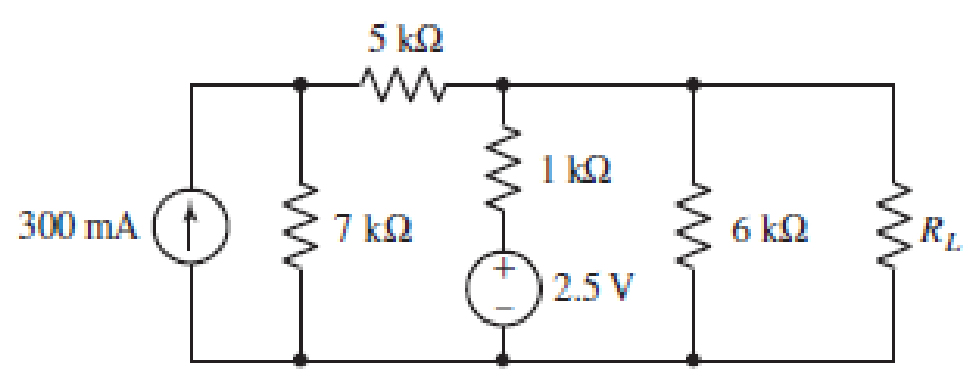
■ FIGURE 5.75
Expert Solution & Answer
Want to see the full answer?
Check out a sample textbook solution
Students have asked these similar questions
how long will it take to charge a 1000μF capacitor through 1 KQ resistor to
full 16V source voltage? d) forever
a) 1000 microseconds
b) 10seconds
c) one day
d) forever
What maximum voltage can be safely applied to series resistors, 1.2 KQ 14 W
and 680 0%W?
a) 9.81V
b) 17.32. V
c)27.07 V
d) 32.52V
When a capacitor is being charged from a 12V power source, the current
flowing through thecapacitor will
a} increase
b} decrease
c) remain the same
d) can't be determined
Calculate the voltmeter reading in the circuit shown in the figure when wiper
arm of the potentiometer is set at 25% up fromthe bottom. note: the
resistance value is 3.3 Kilo-ohms.
9V
a) 2.13 V
b) 3.12 V
c)2.31 V
d) 6.25 V
1k
3k3
Find the current across the resistor 5 52 while the switch
S is open for a long time.
A) (A)
B)(A)
C) (A)
3 V
192
ΖΩΣ
D) (A)
26
3ΩΣ
5 V
E) (A)
4 V
www
:552
Calculate the equivalent impedance of the circuit shown considering the mutual
inductance. (Show your steps in details)
4H
M=0.4H
4H
4 ohm
Zin
4 ohm
Maximum size for new files: 100MB, maximum attachmen
Chapter 5 Solutions
Loose Leaf for Engineering Circuit Analysis Format: Loose-leaf
Ch. 5.1 - For the circuit of Fig. 5.4, use superposition to...Ch. 5.2 - For the circuit of Fig. 5.7, use superposition to...Ch. 5.2 - For the circuit of Fig. 5.18, compute the current...Ch. 5.2 - For the circuit of Fig. 5.20, compute the voltage...Ch. 5.3 - Using repeated source transformations, determine...Ch. 5.3 - Use Thvenins theorem to find the current through...Ch. 5.3 - Determine the Thvenin and Norton equivalents of...Ch. 5.3 - Find the Thvenin equivalent for the network of...Ch. 5.3 - Find the Thvenin equivalent for the network of...Ch. 5.4 - Consider the circuit of Fig. 5.43. FIGURE 5.43...
Ch. 5.5 - Prob. 11PCh. 5 - Linear systems are so easy to work with that...Ch. 5 - Prob. 2ECh. 5 - Prob. 3ECh. 5 - (a) Employ superposition to determine the current...Ch. 5 - (a) Using superposition to consider each source...Ch. 5 - (a) Determine the individual contributions of each...Ch. 5 - (a) Determine the individual contributions of each...Ch. 5 - After studying the circuit of Fig. 5.53, change...Ch. 5 - Consider the three circuits shown in Fig. 5.54....Ch. 5 - (a) Using superposition, determine the voltage...Ch. 5 - Employ superposition principles to obtain a value...Ch. 5 - (a) Employ superposition to determine the...Ch. 5 - Perform an appropriate source transformation on...Ch. 5 - (a) For the circuit of Fig. 5.59, plot iL versus...Ch. 5 - Determine the current labeled I in the circuit of...Ch. 5 - Verify that the power absorbed by the 7 resistor...Ch. 5 - (a) Determine the current labeled i in the circuit...Ch. 5 - (a) Using repeated source transformations, reduce...Ch. 5 - Prob. 19ECh. 5 - (a) Making use of repeated source transformations,...Ch. 5 - Prob. 21ECh. 5 - (a) With the assistance of source transformations,...Ch. 5 - For the circuit in Fig. 5.67 transform all...Ch. 5 - Prob. 24ECh. 5 - (a) Referring to Fig. 5.69, determine the Thevenin...Ch. 5 - (a) With respect to the circuit depicted in Fig....Ch. 5 - (a) Obtain the Norton equivalent of the network...Ch. 5 - (a) Determine the Thevenin equivalent of the...Ch. 5 - Referring to the circuit of Fig. 5.71: (a)...Ch. 5 - Prob. 30ECh. 5 - (a) Employ Thvenins theorem to obtain a...Ch. 5 - Prob. 32ECh. 5 - Determine the Norton equivalent of the circuit...Ch. 5 - For the circuit of Fig. 5.75: (a) Employ Nortons...Ch. 5 - (a) Obtain a value for the Thvenin equivalent...Ch. 5 - Prob. 36ECh. 5 - Obtain a value for the Thvenin equivalent...Ch. 5 - With regard to the network depicted in Fig. 5.79,...Ch. 5 - Determine the Thvenin and Norton equivalents of...Ch. 5 - Determine the Norton equivalent of the circuit...Ch. 5 - Prob. 41ECh. 5 - Determine the Thvenin and Norton equivalents of...Ch. 5 - Prob. 43ECh. 5 - Prob. 44ECh. 5 - Prob. 45ECh. 5 - (a) For the simple circuit of Fig. 5.87, find the...Ch. 5 - For the circuit drawn in Fig. 5.88, (a) determine...Ch. 5 - Study the circuit of Fig. 5.89. (a) Determine the...Ch. 5 - Prob. 49ECh. 5 - Prob. 50ECh. 5 - With reference to the circuit of Fig. 5.91, (a)...Ch. 5 - Prob. 52ECh. 5 - Select a value for RL in Fig. 5.93 such that it...Ch. 5 - Determine what value of resistance would absorb...Ch. 5 - Derive the equations required to convert from a...Ch. 5 - Convert the - (or "-") connected networks in Fig....Ch. 5 - Convert the Y-(or T-) connected networks in Fig....Ch. 5 - For the network of Fig. 5.97, select a value of R...Ch. 5 - For the network of Fig. 5.98, select a value of R...Ch. 5 - Prob. 60ECh. 5 - Calculate Rin as indicated in Fig.5.100. FIGURE...Ch. 5 - Employ Y conversion techniques as appropriate to...Ch. 5 - Prob. 63ECh. 5 - (a) Use appropriate techniques to obtain both the...Ch. 5 - (a) For the network in Fig. 5.104, replace the...Ch. 5 - Prob. 66ECh. 5 - Prob. 67ECh. 5 - A 2.57 load is connected between terminals a and...Ch. 5 - A load resistor is connected across the open...Ch. 5 - A backup is required for the circuit depicted in...Ch. 5 - (a) Explain in general terms how source...Ch. 5 - The load resistor in Fig. 5.108 can safely...Ch. 5 - Prob. 74ECh. 5 - As part of a security system, a very thin 100 ...Ch. 5 - With respect to the circuit in Fig. 5.90, (a)...
Knowledge Booster


Learn more about
Need a deep-dive on the concept behind this application? Look no further. Learn more about this topic, electrical-engineering and related others by exploring similar questions and additional content below.Similar questions
- i. How can four 100 kΩ resistors be connected so that the equivalent resistance of the four equals 250 kΩ? Sketch the arrangement, describe the resistor arrangement in words, and justify your picture by calculating the equivalent resistance. ii. Repeat part i. above with four 100 F capacitors and an equivalent capacitance of 75 F.arrow_forwardDigital lab & design The circuits don’t have to be created in proteus project just a normal drawing on paper will do, thanks. 3)arrow_forwardA moving coil instrument gives a full scale deflection of 30mA, when the potential difference of 60 mV is applied. To measure 500 V on the same scale resistance to be added in series to the circuit. (a) 6.66 kn (b) 16.66 k N (c) 12.5 k N (d) 24.66 k Narrow_forward
- Electical Engineering ============== Needs solutionarrow_forwardA circuit consists of three capacitors and one battery as shown. Calculate the volts associated with the 105 µF capacitor, C2. V = 16 V, C= 125 µF, C2=105 µF, C3=70 µF %3D Numeric entry only. For example: 22.1 C1 C2 ZZZZZA ZZZZZA ZZZ/7 C3arrow_forwarda) Apply nodal analysis to solve for Vx in the circuit of figure Ba. Copyright © The McGraw-Hill Companies, Inc. Permission required for reproduction or display 2 A (4) 10 Ω V 20 Ω 0.2Vx Figure Ba b) A battery has a short-circuit current of 20-A and an open-circuit voltage of 12-V. If the battery is connected to an electric bulb of resistance 2-0, calculate the power dissipated by the bulb. +arrow_forward
- The voltage across a 11 uF capacitor is given by v(1) = -10³sin (10³) volts. Calculate the current in (A) at t= 251.327 ms. **Hint** Remember to include your units and round your answer to two decimal places if needed. **Calculator must be set to radians I=C*(dv/dT)arrow_forwardGiven the circuit below, which of the below value(s) would change if the inductance value were doubled? Assume the circuit has been in this position for some time prior to the switching event happening. Multiple correct answers may exist. Select any/all that apply! t=0 30 12 V (+ 3H 202 40: energy stored prior to the switching event inductor current initial condition time constant energy stored when the system reaches steady-state inductor current final condition None of these answers are correct 402arrow_forward5. A conductive block in the shape of a rectangular solid has a cross-sectional area of 12 cm2 across its width, and a length of 16 cm. The block has a resistance of 220 Ω. The block contains 7e+18 conduction electrons (be careful, this is not "n", although it will help you find "n"). Connecting a battery to the two ends of the block, a potential difference of ΔV= 19 V is maintained along its length. (A)What is the current (in A) in the block? a)0.130 b)0.0337 c)0.0864 d)0.282 e)0.182 f)0.0751 (B)If the current density is uniform, what is its magnitude (in A/m2? a)62.6 b)152 c)72.0 d)235 e)108 f)28.1 (C)What is the drift speed (in m/s) of the conduction electrons? a)0.0402 b)0.0123 c)0.0260 d)0.00481 e)0.0185 f)0.0107 (D)What is the magnitude of the electric field (in N/C or V/m) in the block (Consider this E-field to be constant along the length and remember that there is a formula for the relation between V and E for a constant E-field)? a)103 b)251 c)46.3 d)119 e)387 f)178…arrow_forward
- 5. A conductive block in the shape of a rectangular solid has a cross-sectional area of 12 cm2 across its width, and a length of 16 cm. The block has a resistance of 220 Ω. The block contains 7e+18 conduction electrons (be careful, this is not "n", although it will help you find "n"). Connecting a battery to the two ends of the block, a potential difference of ΔV= 19 V is maintained along its length. (A)What is the current (in A) in the block? a)0.130 b)0.0337 c)0.0864 d)0.282 e)0.182 f)0.0751 (B)If the current density is uniform, what is its magnitude (in A/m2? a)62.6 b)152 c)72.0 d)235 e)108 f)28.1 (C)What is the drift speed (in m/s) of the conduction electrons? a)0.0402 b)0.0123 c)0.0260 d)0.00481 e)0.0185 f)0.0107 (D)What is the magnitude of the electric field (in N/C or V/m) in the block (Consider this E-field to be constant along the length and remember that there is a formula for the relation between V and E for a constant E-field)? a)103 b)251 c)46.3 d)119 e)387 f)178…arrow_forwardQ5. (a) Perform mesh analysis to find the current i, in Figure Q5 (a). 6 V 10 12 v (+ Figure Q5 (a) (b) The following results were obtained from measurements taken between the two terminals of a resistive circuit network Condition 1 12 V O A Condition 2 Terminal Voltage Terminal Current OV 20 A (i) Draw the possible circuit based on the information provided above. If the circuit is connected to an electric bulb of resistance 2 N, determine the power dissipated by the bulb. (ii) wwarrow_forwardV2 i2 R1 R3 V1 + i R4 R2 i3 R5 V3 The analysis of the voltage, V for the electrical circuit shown in figure given above can be expressed in the following three equations: R(-ち)+ &,(i-ち)=7 R3 i, + R4 (i, – iz)+ R (i, – i¿ ) = V, %3D R; iz + R4 (iz – i, ) + R, (iz – 4 ) = V3 where R is the resistance and i is the current. If R1= 20, R2= 10, R3= 25, = 10, R5= 30, Vi=0, V2=0 and V3=200, Solve the system of linear equations above for i, i, and i, by Gauss elimination R4 method. 3.arrow_forward
arrow_back_ios
SEE MORE QUESTIONS
arrow_forward_ios
Recommended textbooks for you
 Introductory Circuit Analysis (13th Edition)Electrical EngineeringISBN:9780133923605Author:Robert L. BoylestadPublisher:PEARSON
 Delmar's Standard Textbook Of ElectricityElectrical EngineeringISBN:9781337900348Author:Stephen L. HermanPublisher:Cengage Learning
 Programmable Logic ControllersElectrical EngineeringISBN:9780073373843Author:Frank D. PetruzellaPublisher:McGraw-Hill Education
 Fundamentals of Electric CircuitsElectrical EngineeringISBN:9780078028229Author:Charles K Alexander, Matthew SadikuPublisher:McGraw-Hill Education
 Electric Circuits. (11th Edition)Electrical EngineeringISBN:9780134746968Author:James W. Nilsson, Susan RiedelPublisher:PEARSON
 Engineering ElectromagneticsElectrical EngineeringISBN:9780078028151Author:Hayt, William H. (william Hart), Jr, BUCK, John A.Publisher:Mcgraw-hill Education,
Introductory Circuit Analysis (13th Edition)
Electrical Engineering
ISBN:9780133923605
Author:Robert L. Boylestad
Publisher:PEARSON
Delmar's Standard Textbook Of Electricity
Electrical Engineering
ISBN:9781337900348
Author:Stephen L. Herman
Publisher:Cengage Learning
Programmable Logic Controllers
Electrical Engineering
ISBN:9780073373843
Author:Frank D. Petruzella
Publisher:McGraw-Hill Education
Fundamentals of Electric Circuits
Electrical Engineering
ISBN:9780078028229
Author:Charles K Alexander, Matthew Sadiku
Publisher:McGraw-Hill Education
Electric Circuits. (11th Edition)
Electrical Engineering
ISBN:9780134746968
Author:James W. Nilsson, Susan Riedel
Publisher:PEARSON
Engineering Electromagnetics
Electrical Engineering
ISBN:9780078028151
Author:Hayt, William H. (william Hart), Jr, BUCK, John A.
Publisher:Mcgraw-hill Education,
Z Parameters - Impedance Parameters; Author: Electrical Engineering Authority;https://www.youtube.com/watch?v=qoD4AoNmySA;License: Standard Youtube License