
Loose Leaf for Engineering Circuit Analysis Format: Loose-leaf
9th Edition
ISBN: 9781259989452
Author: Hayt
Publisher: Mcgraw Hill Publishers
expand_more
expand_more
format_list_bulleted
Concept explainers
Videos
Textbook Question
Chapter 5, Problem 10E
(a) Using superposition, determine the voltage labeled vx in the circuit represented in Fig. 5.55. (b) To what value should the 2 A source be changed to reduce vx by 10%? (c) Verify your answers by performing three dc sweep simulations (one for each source). Submit a labeled schematic, relevant graphical output, and a short description of the results.
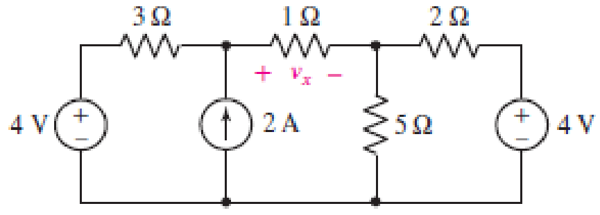
■ FIGURE 5.55
Expert Solution & Answer

Trending nowThis is a popular solution!

Students have asked these similar questions
Hi! I just need an explanation regarding this question :)
Compare the calculated and measured values (for different values of R) and determine whether they agree or are very close in value. Explain your findings.
Directions: The illustration below shows the components of a simple circuit diagram. Choose
from the choices on the left the best term or description that will match each component and
its function. Write your answer on the prescribed box.
• Battery
Component:
Function:
Load
Switch
• Wire
Converts electrical
Component:
Component:
energy into heat,
light, or mechanical
Function:
Function:
energy
• Completes or breaks
circuit by allowing or
stopping current
from flowing
• Provides a route for
Component
Function:
the current to flow
through
• Supplies electrical
energy that causes
current flow
Q: A wood panel containing 16 solar cells. Calculate the total open
circuit voltage and short circuit current coming out of the board and
draw the relationship between current and voltages in the following
cases
a) If you connect each two cells in series and connect the groups in
parallel .
b) If all four cells are connected in parallel and the groups are linked in
succession, noting that each cell has the following characteristics: Vos =
0.75V, Isc = 2 mA
%3D
Chapter 5 Solutions
Loose Leaf for Engineering Circuit Analysis Format: Loose-leaf
Ch. 5.1 - For the circuit of Fig. 5.4, use superposition to...Ch. 5.2 - For the circuit of Fig. 5.7, use superposition to...Ch. 5.2 - For the circuit of Fig. 5.18, compute the current...Ch. 5.2 - For the circuit of Fig. 5.20, compute the voltage...Ch. 5.3 - Using repeated source transformations, determine...Ch. 5.3 - Use Thvenins theorem to find the current through...Ch. 5.3 - Determine the Thvenin and Norton equivalents of...Ch. 5.3 - Find the Thvenin equivalent for the network of...Ch. 5.3 - Find the Thvenin equivalent for the network of...Ch. 5.4 - Consider the circuit of Fig. 5.43. FIGURE 5.43...
Ch. 5.5 - Prob. 11PCh. 5 - Linear systems are so easy to work with that...Ch. 5 - Prob. 2ECh. 5 - Prob. 3ECh. 5 - (a) Employ superposition to determine the current...Ch. 5 - (a) Using superposition to consider each source...Ch. 5 - (a) Determine the individual contributions of each...Ch. 5 - (a) Determine the individual contributions of each...Ch. 5 - After studying the circuit of Fig. 5.53, change...Ch. 5 - Consider the three circuits shown in Fig. 5.54....Ch. 5 - (a) Using superposition, determine the voltage...Ch. 5 - Employ superposition principles to obtain a value...Ch. 5 - (a) Employ superposition to determine the...Ch. 5 - Perform an appropriate source transformation on...Ch. 5 - (a) For the circuit of Fig. 5.59, plot iL versus...Ch. 5 - Determine the current labeled I in the circuit of...Ch. 5 - Verify that the power absorbed by the 7 resistor...Ch. 5 - (a) Determine the current labeled i in the circuit...Ch. 5 - (a) Using repeated source transformations, reduce...Ch. 5 - Prob. 19ECh. 5 - (a) Making use of repeated source transformations,...Ch. 5 - Prob. 21ECh. 5 - (a) With the assistance of source transformations,...Ch. 5 - For the circuit in Fig. 5.67 transform all...Ch. 5 - Prob. 24ECh. 5 - (a) Referring to Fig. 5.69, determine the Thevenin...Ch. 5 - (a) With respect to the circuit depicted in Fig....Ch. 5 - (a) Obtain the Norton equivalent of the network...Ch. 5 - (a) Determine the Thevenin equivalent of the...Ch. 5 - Referring to the circuit of Fig. 5.71: (a)...Ch. 5 - Prob. 30ECh. 5 - (a) Employ Thvenins theorem to obtain a...Ch. 5 - Prob. 32ECh. 5 - Determine the Norton equivalent of the circuit...Ch. 5 - For the circuit of Fig. 5.75: (a) Employ Nortons...Ch. 5 - (a) Obtain a value for the Thvenin equivalent...Ch. 5 - Prob. 36ECh. 5 - Obtain a value for the Thvenin equivalent...Ch. 5 - With regard to the network depicted in Fig. 5.79,...Ch. 5 - Determine the Thvenin and Norton equivalents of...Ch. 5 - Determine the Norton equivalent of the circuit...Ch. 5 - Prob. 41ECh. 5 - Determine the Thvenin and Norton equivalents of...Ch. 5 - Prob. 43ECh. 5 - Prob. 44ECh. 5 - Prob. 45ECh. 5 - (a) For the simple circuit of Fig. 5.87, find the...Ch. 5 - For the circuit drawn in Fig. 5.88, (a) determine...Ch. 5 - Study the circuit of Fig. 5.89. (a) Determine the...Ch. 5 - Prob. 49ECh. 5 - Prob. 50ECh. 5 - With reference to the circuit of Fig. 5.91, (a)...Ch. 5 - Prob. 52ECh. 5 - Select a value for RL in Fig. 5.93 such that it...Ch. 5 - Determine what value of resistance would absorb...Ch. 5 - Derive the equations required to convert from a...Ch. 5 - Convert the - (or "-") connected networks in Fig....Ch. 5 - Convert the Y-(or T-) connected networks in Fig....Ch. 5 - For the network of Fig. 5.97, select a value of R...Ch. 5 - For the network of Fig. 5.98, select a value of R...Ch. 5 - Prob. 60ECh. 5 - Calculate Rin as indicated in Fig.5.100. FIGURE...Ch. 5 - Employ Y conversion techniques as appropriate to...Ch. 5 - Prob. 63ECh. 5 - (a) Use appropriate techniques to obtain both the...Ch. 5 - (a) For the network in Fig. 5.104, replace the...Ch. 5 - Prob. 66ECh. 5 - Prob. 67ECh. 5 - A 2.57 load is connected between terminals a and...Ch. 5 - A load resistor is connected across the open...Ch. 5 - A backup is required for the circuit depicted in...Ch. 5 - (a) Explain in general terms how source...Ch. 5 - The load resistor in Fig. 5.108 can safely...Ch. 5 - Prob. 74ECh. 5 - As part of a security system, a very thin 100 ...Ch. 5 - With respect to the circuit in Fig. 5.90, (a)...
Knowledge Booster


Learn more about
Need a deep-dive on the concept behind this application? Look no further. Learn more about this topic, electrical-engineering and related others by exploring similar questions and additional content below.Similar questions
- answer the following questions using the attached picture. (c) To measure the current flow though R1 and the voltage onR5, how should we connect the ammeter and voltmeter?Draw a circuit diagram showing your answer. (d) What is the ideal impedance of1). an ammeter?2). a voltmeter?arrow_forwardGiven the circuit below. The current through the 100 resistor in the circuit below is 8.0 mA. Determine the 2002 5.0 (2 [www] 10:2 a) total resistance b) total current c) total voltage 30 2 www wwww 5.002 4002arrow_forwardQ17. For the circuit shown in Figure 5.23 calculate (a) the value of resistor Rx such that the total power dissipated in the circuit is 2.5kW, and (b) the current flowing in each of the four resistors. 4 Rq=15 2 a A3=38 2 R2=10 2 Rx 12 14 V2² 250 Varrow_forward
- State which of the following statements are true and which are false. Give reasons for youranswers.a) A very simple circuit consists of a battery connected across a resistor. In this circuit, thebattery and the resistor are both in series and also in parallel.b) A resistor R and a capacitor C connected in series combine as 1RC =1R +1Cc) Natural uranium is not radioactive until it has been processed by enrichment for use infission reactors or bombs.d) Infrared light is more likely to cause electrons to be emitted from a metal than ultravioletlight.e) Special and General Relativity effects both matter for the operation of GPS, the former slowing down the clocks on GPS satellites relative to clocks on Earth and the latter speedingthem up.arrow_forwardPresent all your step by step solutions.arrow_forwardPart A Consider the circuit shown in the figure. A Q-point value for Ic between a minimum of 4 mA and a maximum of 5 mA is required. Assume that resistor values are constant and that B ranges from 95 to 310. It is desired for Rg to have the largest possible value while meeting the other constraints. (Figure 1) Determine the value of Rr. Express your answer to three significant figures and include the appropriate units. • View Available Hint(s) HA ? Rp = 29.9 Submit Previous Answers Request Answer X Incorrect; Try Again; 2 attempts remaining Part B Figure < 1 of 1 Determine the value of RE. Express your answer to three significant figures and include the appropriate units. • View Available Hint(s) +15 V RE = 765 N 1 kQ Submit Previous Answers RB VBEO = 0.7 V v Correct Here we learn how to solve the circuit with the BJT. 5 V RE Provide Feedback P Pearsonarrow_forward
- Answer no. 5arrow_forwardA PMMC instrument gives 27 mA at full scale reading when a potential difference across its terminals is 44mV. Show that how it can be used (a) as an ammeter for the current measurement in the range of 0-3 A (b) as a 0 - 580V range voltmeter for the voltage measurement. (c) find the multiplying factor of shunt and (d) voltage amplification Rsh shunt resistance R1 series resistance multiplying factor for current voltage amplificationarrow_forward6:06 A e-learning.hct.edu.om Question: A group of Students from UTAS (Physics Unit) visit Al Hassan Electrical laboratory. Their supervisor gives them instruction about use of Resistors in different electrical appliances. Students are provided with four resistors R,=50 ohm, R2=70 ohm, R3=380 ohm, R4=70 ohm and a battery of 40 v. i) If students connect these four resistances in series, what is the effective resistance? ii) If students connect these four resistances in parallel, what is the effective resistance? iii) If students connect 40 V battery across series combination, what is the current flowing in the circuit? iv) If students connect 40 V battery across parallel combination, what is the current flowing in the circuit? v) If students connect these four resistances shown below, what is the voltage across points a and d? R2 R1 R4 b. R3 V Finish attempt...arrow_forward
- show your complete solution. need asaparrow_forwardR1 For the above circuit, use the RTh short circuit method to determine the short circuit current, Isc, in Amps across the (a,b) terminals. Round your answer to the nearest single digit decimal place and do not enter units. Given that I = 11A R1 =72 R2 =52 R, =60 RL =52 Determine Isc in Ampsarrow_forwardA PMMC instrument gives 27 mA at full scale reading when a potential difference across its terminals is 38mV. Show that how it can be used (a) as an ammeter for the current measurement in the range of 0–3 A (b) as a 0 – 750V range voltmeter for the voltage measurement. (c) find the multiplying factor of shunt and (d) voltage amplification Rsh shunt resistance R1 series resistance multiplying factor for current voltage amplificationarrow_forward
arrow_back_ios
SEE MORE QUESTIONS
arrow_forward_ios
Recommended textbooks for you
 Introductory Circuit Analysis (13th Edition)Electrical EngineeringISBN:9780133923605Author:Robert L. BoylestadPublisher:PEARSON
 Delmar's Standard Textbook Of ElectricityElectrical EngineeringISBN:9781337900348Author:Stephen L. HermanPublisher:Cengage Learning
 Programmable Logic ControllersElectrical EngineeringISBN:9780073373843Author:Frank D. PetruzellaPublisher:McGraw-Hill Education
 Fundamentals of Electric CircuitsElectrical EngineeringISBN:9780078028229Author:Charles K Alexander, Matthew SadikuPublisher:McGraw-Hill Education
 Electric Circuits. (11th Edition)Electrical EngineeringISBN:9780134746968Author:James W. Nilsson, Susan RiedelPublisher:PEARSON
 Engineering ElectromagneticsElectrical EngineeringISBN:9780078028151Author:Hayt, William H. (william Hart), Jr, BUCK, John A.Publisher:Mcgraw-hill Education,
Introductory Circuit Analysis (13th Edition)
Electrical Engineering
ISBN:9780133923605
Author:Robert L. Boylestad
Publisher:PEARSON
Delmar's Standard Textbook Of Electricity
Electrical Engineering
ISBN:9781337900348
Author:Stephen L. Herman
Publisher:Cengage Learning
Programmable Logic Controllers
Electrical Engineering
ISBN:9780073373843
Author:Frank D. Petruzella
Publisher:McGraw-Hill Education
Fundamentals of Electric Circuits
Electrical Engineering
ISBN:9780078028229
Author:Charles K Alexander, Matthew Sadiku
Publisher:McGraw-Hill Education
Electric Circuits. (11th Edition)
Electrical Engineering
ISBN:9780134746968
Author:James W. Nilsson, Susan Riedel
Publisher:PEARSON
Engineering Electromagnetics
Electrical Engineering
ISBN:9780078028151
Author:Hayt, William H. (william Hart), Jr, BUCK, John A.
Publisher:Mcgraw-hill Education,
Z Parameters - Impedance Parameters; Author: Electrical Engineering Authority;https://www.youtube.com/watch?v=qoD4AoNmySA;License: Standard Youtube License