
Fundamentals of Electric Circuits
6th Edition
ISBN: 9780078028229
Author: Charles K Alexander, Matthew Sadiku
Publisher: McGraw-Hill Education
expand_more
expand_more
format_list_bulleted
Videos
Textbook Question
Chapter 14.6, Problem 9PP
Calculate the resonant frequency of the circuit in Fig. 14.29.
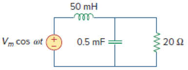
Figure 14.29
Expert Solution & Answer
Want to see the full answer?
Check out a sample textbook solution
Students have asked these similar questions
Example 14.52. An inductor of resistance 102 and inductance 100 mH is in parallel with a 10
nF capacitor. Find the resonant angular frequency
For the signal and circuit of Fig. 14.29, determine the maximum frequency that may
be used. Op-amp slew rate is SR = 0.5 V/μs.
10 km2
www
V₂
(0.02 V,
40-300 x10³)
240 k
m
V₂
Figure 14.29
(__F
14.38
Find the resonant frequency of the circuit in
Fig. 14.78.
Figuro 14 78
L
m
C
ww
R
Chapter 14 Solutions
Fundamentals of Electric Circuits
Ch. 14.2 - Obtain the transfer function VoVs of the RL...Ch. 14.2 - Prob. 2PPCh. 14.4 - Draw the Bode plots for the transfer function...Ch. 14.4 - Sketch the Bode plots for H()=50j(j+4)(j+10)2Ch. 14.4 - Construct the Bode plots for H(s)=10s(s2+80s+400)Ch. 14.4 - Obtain the transfer function H() corresponding to...Ch. 14.5 - A series-connected circuit has R = 4 and L = 25...Ch. 14.6 - A parallel resonant circuit has R = 100 k, L = 50...Ch. 14.6 - Calculate the resonant frequency of the circuit in...Ch. 14.7 - For the circuit in Fig. 14.40, obtain the transfer...
Ch. 14.7 - Design a band-pass filter of the form in Fig....Ch. 14.8 - Design a high-pass filter with a high-frequency...Ch. 14.8 - Design a notch filter based on Fig. 14.47 for 0 =...Ch. 14.9 - Prob. 14PPCh. 14.10 - Obtain the frequency response of the circuit in...Ch. 14.10 - Consider the network in Fig. 14.57. Use PSpice to...Ch. 14.12 - For an FM radio receiver, the incoming wave is in...Ch. 14.12 - Repeat Example 14.18 for band-pass filter BP6....Ch. 14.12 - If each speaker in Fig. 14.66 has an 8- resistance...Ch. 14 - Prob. 1RQCh. 14 - On the Bode magnitude plot, the slope of 1/5+j2...Ch. 14 - On the Bode phase plot for 0.5 50, the slope of...Ch. 14 - How much inductance is needed to resonate at 5 kHz...Ch. 14 - The difference between the half-power frequencies...Ch. 14 - Prob. 6RQCh. 14 - Prob. 7RQCh. 14 - Prob. 8RQCh. 14 - What kind of filter can be used to select a signal...Ch. 14 - A voltage source supplies a signal of constant...Ch. 14 - Find the transfer function Io/Ii of the RL circuit...Ch. 14 - Using Fig. 14.69, design a problem to help other...Ch. 14 - For the circuit shown in Fig. 14.70, find H(s) =...Ch. 14 - Find the transfer function H(s) = Vo/Vi of the...Ch. 14 - For the circuit shown in Fig. 14.72, find H(s) =...Ch. 14 - For the circuit shown in Fig. 14.73, find H(s) =...Ch. 14 - Calculate |H()| if HdB equals (a) 0.1 dB (b) 5 dB...Ch. 14 - Design a problem to help other students calculate...Ch. 14 - A ladder network has a voltage gain of...Ch. 14 - Design a problem to help other students better...Ch. 14 - Sketch the Bode plots for H()=0.2(10+j)j(2+j)Ch. 14 - A transfer function is given by...Ch. 14 - Construct the Bode plots for...Ch. 14 - Draw the Bode plots for H()=250(j+1)j(2+10j+25)Ch. 14 - Prob. 15PCh. 14 - Sketch Bode magnitude and phase plots for...Ch. 14 - Sketch the Bode plots for G(s)=s(s+2)2(s+1), s = jCh. 14 - A linear network has this transfer function...Ch. 14 - Sketch the asymptotic Bode plots of the magnitude...Ch. 14 - Design a more complex problem than given in Prob....Ch. 14 - Sketch the magnitude Bode plot for...Ch. 14 - Find the transfer function H() with the Bode...Ch. 14 - The Bode magnitude plot of H() is shown in Fig....Ch. 14 - The magnitude plot in Fig. 14.76 represents the...Ch. 14 - A series RLC network has R = 2 k, L = 40 mH, and C...Ch. 14 - Design a problem to help other students better...Ch. 14 - Design a series RLC resonant circuit with 0 = 40...Ch. 14 - Design a series RLC circuit with B = 20 rad/s and...Ch. 14 - Let vs = 20 cos(at) V in the circuit of Fig....Ch. 14 - A circuit consisting of a coil with inductance 10...Ch. 14 - Design a parallel resonant RLC circuit with 0 =...Ch. 14 - Design a problem to help other students better...Ch. 14 - A parallel resonant circuit with a bandwidth of 40...Ch. 14 - A parallel RLC circuit has R = 100 k, L = 100 mH,...Ch. 14 - A parallel RLC circuit has R = 10 k, L = 100 mH,...Ch. 14 - It is expected that a parallel RLC resonant...Ch. 14 - Rework Prob. 14.25 if the elements are connected...Ch. 14 - Find the resonant frequency of the circuit in Fig....Ch. 14 - For the tank circuit in Fig. 14.79, find the...Ch. 14 - Prob. 40PCh. 14 - Using Fig. 14.80, design a problem to help other...Ch. 14 - For the circuits in Fig. 14.81, find the resonant...Ch. 14 - Calculate the resonant frequency of each of the...Ch. 14 - For the circuit in Fig. 14.83, find: (a) the...Ch. 14 - For the circuit shown in Fig. 14.84. find 0, B,...Ch. 14 - For the network illustrated in Fig. 14.85, find...Ch. 14 - Prob. 47PCh. 14 - Find the transfer function Vo/Vs of the circuit in...Ch. 14 - Design a problem to help other students better...Ch. 14 - Determine what type of filter is in Fig. 14.87....Ch. 14 - Design an RL low-pass filter that uses a 40-mH...Ch. 14 - Design a problem to help other students better...Ch. 14 - Design a series RLC type band-pass filter with...Ch. 14 - Design a passive band-stop filter with 0 = 10...Ch. 14 - Determine the range of frequencies that will be...Ch. 14 - (a) Show that for a band-pass filter,...Ch. 14 - Determine the center frequency and bandwidth of...Ch. 14 - The circuit parameters for a series RLC band-stop...Ch. 14 - Find the bandwidth and center frequency of the...Ch. 14 - Obtain the transfer function of a high-pass filter...Ch. 14 - Find the transfer function for each of the active...Ch. 14 - The filter in Fig. 14.90(b) has a 3-dB cutoff...Ch. 14 - Design an active first-order high-pass filter with...Ch. 14 - Obtain the transfer function of the active filter...Ch. 14 - A high-pass filter is shown in Fig. 14.92. Show...Ch. 14 - A general first-order filter is shown in Fig....Ch. 14 - Design an active low-pass filter with dc gain of...Ch. 14 - Design a problem to help other students better...Ch. 14 - Design the filter in Fig. 14.94 to meet the...Ch. 14 - A second-order active filter known as a...Ch. 14 - Use magnitude and frequency scaling on the circuit...Ch. 14 - Design a problem to help other students better...Ch. 14 - Calculate the values of R, L, and C that will...Ch. 14 - Prob. 74PCh. 14 - In an RLC circuit, R = 20 , L = 4 H, and C = 1 F....Ch. 14 - Given a parallel RLC circuit with R = 5 k, L = 10...Ch. 14 - A series RLC circuit has R = 10 , 0 = 40 rad/s,...Ch. 14 - Redesign the circuit in Fig. 14.85 so that all...Ch. 14 - Refer to the network in Fig. 14.96. (a) Find...Ch. 14 - (a) For the circuit in Fig. 14.97, draw the new...Ch. 14 - The circuit shown in Fig. 14.98 has the impedance...Ch. 14 - Scale the low-pass active filter in Fig. 14.99 so...Ch. 14 - The op amp circuit in Fig. 14.100 is to be...Ch. 14 - Using PSpice or MultiSim, obtain the frequency...Ch. 14 - Use PSpice or MultiSim to obtain the magnitude and...Ch. 14 - Using Fig. 14.103, design a problem to help other...Ch. 14 - In the interval 0.1 f 100 Hz, plot the response...Ch. 14 - Use PSpice or MultiSim to generate the magnitude...Ch. 14 - Obtain the magnitude plot of the response Vo in...Ch. 14 - Obtain the frequency response of the circuit in...Ch. 14 - For the tank circuit of Fig. 14.79, obtain the...Ch. 14 - Using PSpice or MultiSim, plot the magnitude of...Ch. 14 - For the phase shifter circuit shown in Fig....Ch. 14 - For an emergency situation, an engineer needs to...Ch. 14 - A series-tuned antenna circuit consists of a...Ch. 14 - The crossover circuit in Fig. 14.108 is a low-pass...Ch. 14 - The crossover circuit in Fig. 14.109 is a...Ch. 14 - A certain electronic test circuit produced a...Ch. 14 - In an electronic device, a series circuit is...Ch. 14 - In a certain application, a simple RC low-pass...Ch. 14 - In an amplifier circuit, a simple RC high-pass...Ch. 14 - Practical RC filter design should allow for source...Ch. 14 - The RC circuit in Fig. 14.111 is used for a lead...Ch. 14 - A low-quality-factor, double-tuned band-pass...
Knowledge Booster


Learn more about
Need a deep-dive on the concept behind this application? Look no further. Learn more about this topic, electrical-engineering and related others by exploring similar questions and additional content below.Similar questions
- EXAMPLE 14.31 Find the input voltage of the circuit of Fig. 14.65 if v. = 50 sin(3771 + 30°) V, = 30 sin(3771 + 60°) f = 60 Hz osvol Jaw, we e in from the to the So ds in V= sin a to 61arrow_forward14.9 A ladder network has a voltage gain of 10 H(@) (1 + jw)(10 + jw) Sketch the Bode plots for the gain.arrow_forwardA hollow pipe (such as an organ pipe open at both ends) is made to go into resonance at frequency f open. One end of the pipe is now covered and the pipe is again made to go into resonance, this time at frequency f closed. Both resonances are first harmonics. How do these two resonances compare? (a) They are the same. (b) f open = 2f closed (c) f closed = 2f open (d) f open = f closed (e) fclosed = 3/2 fopenarrow_forward
- V:OV 3G !!.: Classroom > docs.google.com • * الاسم الرباعي الكامل Your answer Engineering and Numerical Analysis Lecture: Safa Al-waily 01| plot the Amplidude s phase spectyum (signal & double side) Q2 |Fimd x plot h complex form of (Fis) for he fenetion. Scanned by TapScanner 1 Add file Submit Clear form Never submit passwords through Google Forms. + •.. 5arrow_forward4. The Bode plot shown below represents the voltage gain of a particular amplifier. Sketch the input and output waveforms, v,() and v(1) if the input to the amplifier is v, (1) = 10 + 10cos(400t + 60°) mV. Use the graph paper on the next page for your sketches and label the minimum and maximum value for each waveform. 60 Bode Diagram 58 56 54 52 50 48 46 44 42 40 -5 -10 -15 -20 -25 -30 -35 -40 -45 -50 -55 -60 100 101 102 Frequency (rad/s) 10 104 105 (Bap) aseud Magnitude (dB)arrow_forwardIt refers to the mixing of frequencies in a nonlinear device or the use of nonlinear mixing to convert one frequency to another. Select your answer. Frequency transformation Frequency mixing Superheterodyne Heterodynearrow_forward
- Asenes circuit comprises an inductor, of resistance 10 Q and inductance 159 µH, and a variable capacitor connected to a 50 mV sınusoidal supply of frequency 1 MHz What value of capactance will result in resonant conditions and what will then be the current? For what values of capacitance will the current at this frequency be reduced to 10% of its value at resonance?arrow_forwardThe bandwidth of a series resonant circuit is 400 Hz. a. If the resonant frequency is 4000 Hz, what is the value of Qs? 10 , what is the value of X, at resonance? b. If R c. Find the inductance L =arrow_forward100 μΗ Vs 2.2 mH 0.1 uF 100 µF (b) (a) FIGURE 14.45 10. Determine the resonant frequency for the circuit shown in Figure 14.45b. 17. Calculate the values of X, and X, for the circuit shown in Figure 14.42a when it is op- erating at its resonant frequency. 11. 10h uhen it is oneratingarrow_forward
- Solve for the following a.) Resonant Frequency b.) total impedance at resonant frequency c.) total power @ resonant frequency with Vs = 1 <0 degrees, (Vrms)arrow_forwardwhere R = 4 Ohm, L 40 mH and C-30 nF. Figure Q1. Electrical circult of the given question a) Derive the impedance and admittance functions in terms of frequency. b) Calculate the numerical values of the resonant frequency, the dynamic impedance and the bandwidth.arrow_forwardCritically analyse the principles of circuit theory to explain series resonant circuit. Deriveexpression for resonant frequency and evaluate the resonant frequency and current flowing atresonance in a series a.c circuit consisting of a coil of resistance 4 ohm , inductance 70mH and capacitance0.06 uF if the supply voltage is 100Varrow_forward
arrow_back_ios
SEE MORE QUESTIONS
arrow_forward_ios
Recommended textbooks for you
 Introductory Circuit Analysis (13th Edition)Electrical EngineeringISBN:9780133923605Author:Robert L. BoylestadPublisher:PEARSON
 Delmar's Standard Textbook Of ElectricityElectrical EngineeringISBN:9781337900348Author:Stephen L. HermanPublisher:Cengage Learning
 Programmable Logic ControllersElectrical EngineeringISBN:9780073373843Author:Frank D. PetruzellaPublisher:McGraw-Hill Education
 Fundamentals of Electric CircuitsElectrical EngineeringISBN:9780078028229Author:Charles K Alexander, Matthew SadikuPublisher:McGraw-Hill Education
 Electric Circuits. (11th Edition)Electrical EngineeringISBN:9780134746968Author:James W. Nilsson, Susan RiedelPublisher:PEARSON
 Engineering ElectromagneticsElectrical EngineeringISBN:9780078028151Author:Hayt, William H. (william Hart), Jr, BUCK, John A.Publisher:Mcgraw-hill Education,
Introductory Circuit Analysis (13th Edition)
Electrical Engineering
ISBN:9780133923605
Author:Robert L. Boylestad
Publisher:PEARSON
Delmar's Standard Textbook Of Electricity
Electrical Engineering
ISBN:9781337900348
Author:Stephen L. Herman
Publisher:Cengage Learning
Programmable Logic Controllers
Electrical Engineering
ISBN:9780073373843
Author:Frank D. Petruzella
Publisher:McGraw-Hill Education
Fundamentals of Electric Circuits
Electrical Engineering
ISBN:9780078028229
Author:Charles K Alexander, Matthew Sadiku
Publisher:McGraw-Hill Education
Electric Circuits. (11th Edition)
Electrical Engineering
ISBN:9780134746968
Author:James W. Nilsson, Susan Riedel
Publisher:PEARSON
Engineering Electromagnetics
Electrical Engineering
ISBN:9780078028151
Author:Hayt, William H. (william Hart), Jr, BUCK, John A.
Publisher:Mcgraw-hill Education,
Routh Hurwitz Stability Criterion Basic Worked Example; Author: The Complete Guide to Everything;https://www.youtube.com/watch?v=CzzsR5FT-8U;License: Standard Youtube License