
Fundamentals of Electric Circuits
6th Edition
ISBN: 9780078028229
Author: Charles K Alexander, Matthew Sadiku
Publisher: McGraw-Hill Education
expand_more
expand_more
format_list_bulleted
Videos
Textbook Question
Chapter 14.12, Problem 18PP
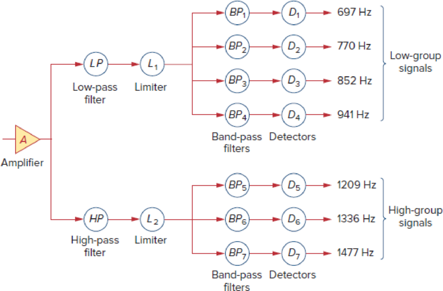
Repeat Example 14.18 for band-pass filter BP6.
Using the standard 600-Ω resistor used in telephone circuits and a series RLC circuit, design the band-pass filter BP2 in Fig. 14.65
Figure 14.65
Block diagram of detection scheme.
Expert Solution & Answer
Want to see the full answer?
Check out a sample textbook solution
Students have asked these similar questions
Q4
Design an active highpass filter with a gain of 10, a corner frequency of 2 kHz, and a gain roll-off
rate of 40 dB/decade.
Design a low pass filter for a cutoff
frequency of 15MHZ. Confirm your answer
with a simulation and construct your Bode
plot. Also, specify the schematic of your
circuit, the transfer function, the maximum
value of the transfer function, and the value
of the transfer function for the cutoff
frequency. For your design keep in mind
that the internal resistance of the signal
source is 75 Q and the load has a value of 3
kQ. (To do the simulation you can use the
multisim software)
I want the answer in detail and as quickly as
possible please
Q/ Using capacitors and resistors, design
A - (band-pass filters) with Fl=108HZ and
Fh=112HZ.
B - Design (band-pass filters) with Fl = 218HZ
and Fh = 223HZ.
%3D
((And make sure that the values are available in
the market))
Chapter 14 Solutions
Fundamentals of Electric Circuits
Ch. 14.2 - Obtain the transfer function VoVs of the RL...Ch. 14.2 - Prob. 2PPCh. 14.4 - Draw the Bode plots for the transfer function...Ch. 14.4 - Sketch the Bode plots for H()=50j(j+4)(j+10)2Ch. 14.4 - Construct the Bode plots for H(s)=10s(s2+80s+400)Ch. 14.4 - Obtain the transfer function H() corresponding to...Ch. 14.5 - A series-connected circuit has R = 4 and L = 25...Ch. 14.6 - A parallel resonant circuit has R = 100 k, L = 50...Ch. 14.6 - Calculate the resonant frequency of the circuit in...Ch. 14.7 - For the circuit in Fig. 14.40, obtain the transfer...
Ch. 14.7 - Design a band-pass filter of the form in Fig....Ch. 14.8 - Design a high-pass filter with a high-frequency...Ch. 14.8 - Design a notch filter based on Fig. 14.47 for 0 =...Ch. 14.9 - Prob. 14PPCh. 14.10 - Obtain the frequency response of the circuit in...Ch. 14.10 - Consider the network in Fig. 14.57. Use PSpice to...Ch. 14.12 - For an FM radio receiver, the incoming wave is in...Ch. 14.12 - Repeat Example 14.18 for band-pass filter BP6....Ch. 14.12 - If each speaker in Fig. 14.66 has an 8- resistance...Ch. 14 - Prob. 1RQCh. 14 - On the Bode magnitude plot, the slope of 1/5+j2...Ch. 14 - On the Bode phase plot for 0.5 50, the slope of...Ch. 14 - How much inductance is needed to resonate at 5 kHz...Ch. 14 - The difference between the half-power frequencies...Ch. 14 - Prob. 6RQCh. 14 - Prob. 7RQCh. 14 - Prob. 8RQCh. 14 - What kind of filter can be used to select a signal...Ch. 14 - A voltage source supplies a signal of constant...Ch. 14 - Find the transfer function Io/Ii of the RL circuit...Ch. 14 - Using Fig. 14.69, design a problem to help other...Ch. 14 - For the circuit shown in Fig. 14.70, find H(s) =...Ch. 14 - Find the transfer function H(s) = Vo/Vi of the...Ch. 14 - For the circuit shown in Fig. 14.72, find H(s) =...Ch. 14 - For the circuit shown in Fig. 14.73, find H(s) =...Ch. 14 - Calculate |H()| if HdB equals (a) 0.1 dB (b) 5 dB...Ch. 14 - Design a problem to help other students calculate...Ch. 14 - A ladder network has a voltage gain of...Ch. 14 - Design a problem to help other students better...Ch. 14 - Sketch the Bode plots for H()=0.2(10+j)j(2+j)Ch. 14 - A transfer function is given by...Ch. 14 - Construct the Bode plots for...Ch. 14 - Draw the Bode plots for H()=250(j+1)j(2+10j+25)Ch. 14 - Prob. 15PCh. 14 - Sketch Bode magnitude and phase plots for...Ch. 14 - Sketch the Bode plots for G(s)=s(s+2)2(s+1), s = jCh. 14 - A linear network has this transfer function...Ch. 14 - Sketch the asymptotic Bode plots of the magnitude...Ch. 14 - Design a more complex problem than given in Prob....Ch. 14 - Sketch the magnitude Bode plot for...Ch. 14 - Find the transfer function H() with the Bode...Ch. 14 - The Bode magnitude plot of H() is shown in Fig....Ch. 14 - The magnitude plot in Fig. 14.76 represents the...Ch. 14 - A series RLC network has R = 2 k, L = 40 mH, and C...Ch. 14 - Design a problem to help other students better...Ch. 14 - Design a series RLC resonant circuit with 0 = 40...Ch. 14 - Design a series RLC circuit with B = 20 rad/s and...Ch. 14 - Let vs = 20 cos(at) V in the circuit of Fig....Ch. 14 - A circuit consisting of a coil with inductance 10...Ch. 14 - Design a parallel resonant RLC circuit with 0 =...Ch. 14 - Design a problem to help other students better...Ch. 14 - A parallel resonant circuit with a bandwidth of 40...Ch. 14 - A parallel RLC circuit has R = 100 k, L = 100 mH,...Ch. 14 - A parallel RLC circuit has R = 10 k, L = 100 mH,...Ch. 14 - It is expected that a parallel RLC resonant...Ch. 14 - Rework Prob. 14.25 if the elements are connected...Ch. 14 - Find the resonant frequency of the circuit in Fig....Ch. 14 - For the tank circuit in Fig. 14.79, find the...Ch. 14 - Prob. 40PCh. 14 - Using Fig. 14.80, design a problem to help other...Ch. 14 - For the circuits in Fig. 14.81, find the resonant...Ch. 14 - Calculate the resonant frequency of each of the...Ch. 14 - For the circuit in Fig. 14.83, find: (a) the...Ch. 14 - For the circuit shown in Fig. 14.84. find 0, B,...Ch. 14 - For the network illustrated in Fig. 14.85, find...Ch. 14 - Prob. 47PCh. 14 - Find the transfer function Vo/Vs of the circuit in...Ch. 14 - Design a problem to help other students better...Ch. 14 - Determine what type of filter is in Fig. 14.87....Ch. 14 - Design an RL low-pass filter that uses a 40-mH...Ch. 14 - Design a problem to help other students better...Ch. 14 - Design a series RLC type band-pass filter with...Ch. 14 - Design a passive band-stop filter with 0 = 10...Ch. 14 - Determine the range of frequencies that will be...Ch. 14 - (a) Show that for a band-pass filter,...Ch. 14 - Determine the center frequency and bandwidth of...Ch. 14 - The circuit parameters for a series RLC band-stop...Ch. 14 - Find the bandwidth and center frequency of the...Ch. 14 - Obtain the transfer function of a high-pass filter...Ch. 14 - Find the transfer function for each of the active...Ch. 14 - The filter in Fig. 14.90(b) has a 3-dB cutoff...Ch. 14 - Design an active first-order high-pass filter with...Ch. 14 - Obtain the transfer function of the active filter...Ch. 14 - A high-pass filter is shown in Fig. 14.92. Show...Ch. 14 - A general first-order filter is shown in Fig....Ch. 14 - Design an active low-pass filter with dc gain of...Ch. 14 - Design a problem to help other students better...Ch. 14 - Design the filter in Fig. 14.94 to meet the...Ch. 14 - A second-order active filter known as a...Ch. 14 - Use magnitude and frequency scaling on the circuit...Ch. 14 - Design a problem to help other students better...Ch. 14 - Calculate the values of R, L, and C that will...Ch. 14 - Prob. 74PCh. 14 - In an RLC circuit, R = 20 , L = 4 H, and C = 1 F....Ch. 14 - Given a parallel RLC circuit with R = 5 k, L = 10...Ch. 14 - A series RLC circuit has R = 10 , 0 = 40 rad/s,...Ch. 14 - Redesign the circuit in Fig. 14.85 so that all...Ch. 14 - Refer to the network in Fig. 14.96. (a) Find...Ch. 14 - (a) For the circuit in Fig. 14.97, draw the new...Ch. 14 - The circuit shown in Fig. 14.98 has the impedance...Ch. 14 - Scale the low-pass active filter in Fig. 14.99 so...Ch. 14 - The op amp circuit in Fig. 14.100 is to be...Ch. 14 - Using PSpice or MultiSim, obtain the frequency...Ch. 14 - Use PSpice or MultiSim to obtain the magnitude and...Ch. 14 - Using Fig. 14.103, design a problem to help other...Ch. 14 - In the interval 0.1 f 100 Hz, plot the response...Ch. 14 - Use PSpice or MultiSim to generate the magnitude...Ch. 14 - Obtain the magnitude plot of the response Vo in...Ch. 14 - Obtain the frequency response of the circuit in...Ch. 14 - For the tank circuit of Fig. 14.79, obtain the...Ch. 14 - Using PSpice or MultiSim, plot the magnitude of...Ch. 14 - For the phase shifter circuit shown in Fig....Ch. 14 - For an emergency situation, an engineer needs to...Ch. 14 - A series-tuned antenna circuit consists of a...Ch. 14 - The crossover circuit in Fig. 14.108 is a low-pass...Ch. 14 - The crossover circuit in Fig. 14.109 is a...Ch. 14 - A certain electronic test circuit produced a...Ch. 14 - In an electronic device, a series circuit is...Ch. 14 - In a certain application, a simple RC low-pass...Ch. 14 - In an amplifier circuit, a simple RC high-pass...Ch. 14 - Practical RC filter design should allow for source...Ch. 14 - The RC circuit in Fig. 14.111 is used for a lead...Ch. 14 - A low-quality-factor, double-tuned band-pass...
Knowledge Booster


Learn more about
Need a deep-dive on the concept behind this application? Look no further. Learn more about this topic, electrical-engineering and related others by exploring similar questions and additional content below.Similar questions
- (b) Analyse and obtain the transfer function for the filter as shown in Figure Q2(b). R₁ VW HH R₂ W Figure Q2 (b)arrow_forwardDesign a series RLC bandpass filter (see 14.19[a]) with aquality of 2 and a center frequency of 8 kHz, using a 5 nF capacitor.1. a) Draw your circuit, labeling the component values and outputvoltage.2. b) For the filter in part (a), calculate the bandwidth and the valuesof the two cutoff frequencies.arrow_forward4. The Bode plot shown below represents the voltage gain of a particular amplifier. Sketch the input and output waveforms, v,() and v(1) if the input to the amplifier is v, (1) = 10 + 10cos(400t + 60°) mV. Use the graph paper on the next page for your sketches and label the minimum and maximum value for each waveform. 60 Bode Diagram 58 56 54 52 50 48 46 44 42 40 -5 -10 -15 -20 -25 -30 -35 -40 -45 -50 -55 -60 100 101 102 Frequency (rad/s) 10 104 105 (Bap) aseud Magnitude (dB)arrow_forward
- Identify the 3rd order transfer function ?(?) of the op amp from the Bode plot of the open-loop response in the spec sheet:arrow_forward14.13 Using a 5 mH inductor, design a high-pass, RL, pas- DESIGH sive filter with a cutoff frequency of 25 krad/s. a) Specify the value of the resistance. PROBLEM PSPICE ULTISIA b) Assume the filter is connected to a pure resistive load. The cutoff frequency is not to drop below 24 krad/s. What is the smallest load resistor that can be connected across the output terminals of the filter?arrow_forwardVS+ -SA V1 5 V2 5 .ac dec 100 1 1Meg lib LM741.mod VIN V3 R1 C1 1.3k 0.12μ AC 1 Figure. Active Band Pass Filter R2 1.3k C2 0.12μ Imax -VS+ -SA U1 VOUT LM741/NS Provide the following expressions or values as required: VOUT VIN ) Expression for the maximum gain/magnitude G = ) Expression for the natural frequency fo and its corresponding value ) Expression for selectivity Q and its corresponding value and its corresponding valuearrow_forward
- Answer the following wuth illustration and solutions. 1.) A second-order band pass filter is to be constructed using RC components that will only allow a range of frequencies to pass above 500Hz and below 1.5kHz. Assuming that both the resistor have values of 1kohms, calculate the values of the two capacitors required. Find also the center frequency of the two frequencies. This is the example/guide that might help.arrow_forwardFigures (a) to (e) below show the asymptotic Bode diagrams (magnitude and phase) of the constituent parts of five different open-loop transfer functions, ??(?). The Bode diagrams are colour coded. Write the transfer function corresponding to the pair of Bode plots in the space provided to the right of each figure. No need to show any working – just write the standard form of transfer function equation for each diagram. please help with b, c and darrow_forwardActivity 4: For the low-pass active filter shown below, the transfer function is expressed as: V. Vi Zr + Zc where: 106 Zc jw rad w = angular frequency in [ ZR = 2000 , ZR Vị o- Vo Zc 4-A) Show that the can be written as: V. 500 Vi 500 + jw 4-B) What should be the value of w so that the magnitude of 2 is a Vị 4-C) With w = 1250 rad/s, and V; = 9e1.8 – j10 volts, evaluate the magnitude and phase of V, Vo (Hint: evaluate Vị in polar form, and V; in polar form, then V, = x V; ) Vi 4-D) When 4 modules of this filter are cascaded, the total transfer function will be Use de Moivre's Theorem to find the expression of the total transfer function in polar form. Then, find determine the value of w so that the magnitude of the total transfer function is ? 10arrow_forward
- What is the definition of resonant frequencies, cut-off frequencies, bandwidth, andquality factor of series and parallel RLC circuits.And how do you determine the circuit conditions at the resonant and cut-off frequencies. (Answer in long paragraph form)arrow_forwardDesign an active high-pass filter circuit using op-amp and calculate the value ofthe capacitor, resistor needed that will produce the cut-off frequency of 331 Hz.arrow_forwardThe Band Stop Filter, (BSF) is another type of frequency selective circuit that functions in exactly the opposite way to the Band Pass Filter we studied before. The band stop filter, also known as a band reject filter, passes all frequencies with the exception of those within a specified stop band which are greatly attenuated. By combining a basic RC low-pass filter with a RC high-pass filter we can form a simple band-stop filter that can block or at least severely attenuate a range or band of frequencies within the two cut-off frequency points. This derivable illustrates criteria to proceed applying next steps of this project. Students have to do the schematic of the proposed circuit as well as the detailed design equations and required simulations Submit (below) a report with the following: e Middle2020 1. Research the formula of the cut-off frequency of RC filter. 2. Hand calculation for different filter's components 3. Detailed list of components and their values (use a table…arrow_forward
arrow_back_ios
SEE MORE QUESTIONS
arrow_forward_ios
Recommended textbooks for you
 Introductory Circuit Analysis (13th Edition)Electrical EngineeringISBN:9780133923605Author:Robert L. BoylestadPublisher:PEARSON
 Delmar's Standard Textbook Of ElectricityElectrical EngineeringISBN:9781337900348Author:Stephen L. HermanPublisher:Cengage Learning
 Programmable Logic ControllersElectrical EngineeringISBN:9780073373843Author:Frank D. PetruzellaPublisher:McGraw-Hill Education
 Fundamentals of Electric CircuitsElectrical EngineeringISBN:9780078028229Author:Charles K Alexander, Matthew SadikuPublisher:McGraw-Hill Education
 Electric Circuits. (11th Edition)Electrical EngineeringISBN:9780134746968Author:James W. Nilsson, Susan RiedelPublisher:PEARSON
 Engineering ElectromagneticsElectrical EngineeringISBN:9780078028151Author:Hayt, William H. (william Hart), Jr, BUCK, John A.Publisher:Mcgraw-hill Education,
Introductory Circuit Analysis (13th Edition)
Electrical Engineering
ISBN:9780133923605
Author:Robert L. Boylestad
Publisher:PEARSON
Delmar's Standard Textbook Of Electricity
Electrical Engineering
ISBN:9781337900348
Author:Stephen L. Herman
Publisher:Cengage Learning
Programmable Logic Controllers
Electrical Engineering
ISBN:9780073373843
Author:Frank D. Petruzella
Publisher:McGraw-Hill Education
Fundamentals of Electric Circuits
Electrical Engineering
ISBN:9780078028229
Author:Charles K Alexander, Matthew Sadiku
Publisher:McGraw-Hill Education
Electric Circuits. (11th Edition)
Electrical Engineering
ISBN:9780134746968
Author:James W. Nilsson, Susan Riedel
Publisher:PEARSON
Engineering Electromagnetics
Electrical Engineering
ISBN:9780078028151
Author:Hayt, William H. (william Hart), Jr, BUCK, John A.
Publisher:Mcgraw-hill Education,
Why Use Bode Plots? | Understanding Bode Plots, Part 1; Author: MATLAB;https://www.youtube.com/watch?v=F6-EaZobHNk;License: Standard Youtube License