
Fundamentals of Electric Circuits
6th Edition
ISBN: 9780078028229
Author: Charles K Alexander, Matthew Sadiku
Publisher: McGraw-Hill Education
expand_more
expand_more
format_list_bulleted
Videos
Textbook Question
Chapter 14, Problem 45P
For the circuit shown in Fig. 14.84. find ω0, B, and Q, as seen by the voltage across the inductor.
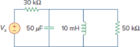
Figure 14.84
Expert Solution & Answer
Want to see the full answer?
Check out a sample textbook solution
Students have asked these similar questions
Let Zeq be the equivalent impedance of a series connection of an
inductor with inductance L and a capacitor with capacitance C. At
w=1/√√LC, the equivalent impedance is given by _
O
a. Zeq = 00
O b. Zeq = 0
O c. Zeq = 0.5
O
d. Zeq = 1
Determine if each statement is True or False; if false, please explain whya) A forced oscillator is when a system is being yelled at to perform a specific motion.b) Impedance is a measure of the total resistance a RLC series circuit has towards current.c) The phase angle tells us how “out-of-phase” the charge on the capacitor iswith the driving voltage.
An inductor with L = 150mH and r = 200(Omega) is in series with a capacitor, a resistor, and a generator of w = 1000 rad / s The voltage across the inductor Vind is measured to be 10.87 V, VR is measured to be 4.65 , and Vc is measured to be 5.96 V. What is the generator voltage V? (Hint: This is the measurement to be performed in this laboratory for LCR circuits. Use the appropriate equations to find VL and Vr' and then use them and the values of VR and VC to calculate V.)
Chapter 14 Solutions
Fundamentals of Electric Circuits
Ch. 14.2 - Obtain the transfer function VoVs of the RL...Ch. 14.2 - Prob. 2PPCh. 14.4 - Draw the Bode plots for the transfer function...Ch. 14.4 - Sketch the Bode plots for H()=50j(j+4)(j+10)2Ch. 14.4 - Construct the Bode plots for H(s)=10s(s2+80s+400)Ch. 14.4 - Obtain the transfer function H() corresponding to...Ch. 14.5 - A series-connected circuit has R = 4 and L = 25...Ch. 14.6 - A parallel resonant circuit has R = 100 k, L = 50...Ch. 14.6 - Calculate the resonant frequency of the circuit in...Ch. 14.7 - For the circuit in Fig. 14.40, obtain the transfer...
Ch. 14.7 - Design a band-pass filter of the form in Fig....Ch. 14.8 - Design a high-pass filter with a high-frequency...Ch. 14.8 - Design a notch filter based on Fig. 14.47 for 0 =...Ch. 14.9 - Prob. 14PPCh. 14.10 - Obtain the frequency response of the circuit in...Ch. 14.10 - Consider the network in Fig. 14.57. Use PSpice to...Ch. 14.12 - For an FM radio receiver, the incoming wave is in...Ch. 14.12 - Repeat Example 14.18 for band-pass filter BP6....Ch. 14.12 - If each speaker in Fig. 14.66 has an 8- resistance...Ch. 14 - Prob. 1RQCh. 14 - On the Bode magnitude plot, the slope of 1/5+j2...Ch. 14 - On the Bode phase plot for 0.5 50, the slope of...Ch. 14 - How much inductance is needed to resonate at 5 kHz...Ch. 14 - The difference between the half-power frequencies...Ch. 14 - Prob. 6RQCh. 14 - Prob. 7RQCh. 14 - Prob. 8RQCh. 14 - What kind of filter can be used to select a signal...Ch. 14 - A voltage source supplies a signal of constant...Ch. 14 - Find the transfer function Io/Ii of the RL circuit...Ch. 14 - Using Fig. 14.69, design a problem to help other...Ch. 14 - For the circuit shown in Fig. 14.70, find H(s) =...Ch. 14 - Find the transfer function H(s) = Vo/Vi of the...Ch. 14 - For the circuit shown in Fig. 14.72, find H(s) =...Ch. 14 - For the circuit shown in Fig. 14.73, find H(s) =...Ch. 14 - Calculate |H()| if HdB equals (a) 0.1 dB (b) 5 dB...Ch. 14 - Design a problem to help other students calculate...Ch. 14 - A ladder network has a voltage gain of...Ch. 14 - Design a problem to help other students better...Ch. 14 - Sketch the Bode plots for H()=0.2(10+j)j(2+j)Ch. 14 - A transfer function is given by...Ch. 14 - Construct the Bode plots for...Ch. 14 - Draw the Bode plots for H()=250(j+1)j(2+10j+25)Ch. 14 - Prob. 15PCh. 14 - Sketch Bode magnitude and phase plots for...Ch. 14 - Sketch the Bode plots for G(s)=s(s+2)2(s+1), s = jCh. 14 - A linear network has this transfer function...Ch. 14 - Sketch the asymptotic Bode plots of the magnitude...Ch. 14 - Design a more complex problem than given in Prob....Ch. 14 - Sketch the magnitude Bode plot for...Ch. 14 - Find the transfer function H() with the Bode...Ch. 14 - The Bode magnitude plot of H() is shown in Fig....Ch. 14 - The magnitude plot in Fig. 14.76 represents the...Ch. 14 - A series RLC network has R = 2 k, L = 40 mH, and C...Ch. 14 - Design a problem to help other students better...Ch. 14 - Design a series RLC resonant circuit with 0 = 40...Ch. 14 - Design a series RLC circuit with B = 20 rad/s and...Ch. 14 - Let vs = 20 cos(at) V in the circuit of Fig....Ch. 14 - A circuit consisting of a coil with inductance 10...Ch. 14 - Design a parallel resonant RLC circuit with 0 =...Ch. 14 - Design a problem to help other students better...Ch. 14 - A parallel resonant circuit with a bandwidth of 40...Ch. 14 - A parallel RLC circuit has R = 100 k, L = 100 mH,...Ch. 14 - A parallel RLC circuit has R = 10 k, L = 100 mH,...Ch. 14 - It is expected that a parallel RLC resonant...Ch. 14 - Rework Prob. 14.25 if the elements are connected...Ch. 14 - Find the resonant frequency of the circuit in Fig....Ch. 14 - For the tank circuit in Fig. 14.79, find the...Ch. 14 - Prob. 40PCh. 14 - Using Fig. 14.80, design a problem to help other...Ch. 14 - For the circuits in Fig. 14.81, find the resonant...Ch. 14 - Calculate the resonant frequency of each of the...Ch. 14 - For the circuit in Fig. 14.83, find: (a) the...Ch. 14 - For the circuit shown in Fig. 14.84. find 0, B,...Ch. 14 - For the network illustrated in Fig. 14.85, find...Ch. 14 - Prob. 47PCh. 14 - Find the transfer function Vo/Vs of the circuit in...Ch. 14 - Design a problem to help other students better...Ch. 14 - Determine what type of filter is in Fig. 14.87....Ch. 14 - Design an RL low-pass filter that uses a 40-mH...Ch. 14 - Design a problem to help other students better...Ch. 14 - Design a series RLC type band-pass filter with...Ch. 14 - Design a passive band-stop filter with 0 = 10...Ch. 14 - Determine the range of frequencies that will be...Ch. 14 - (a) Show that for a band-pass filter,...Ch. 14 - Determine the center frequency and bandwidth of...Ch. 14 - The circuit parameters for a series RLC band-stop...Ch. 14 - Find the bandwidth and center frequency of the...Ch. 14 - Obtain the transfer function of a high-pass filter...Ch. 14 - Find the transfer function for each of the active...Ch. 14 - The filter in Fig. 14.90(b) has a 3-dB cutoff...Ch. 14 - Design an active first-order high-pass filter with...Ch. 14 - Obtain the transfer function of the active filter...Ch. 14 - A high-pass filter is shown in Fig. 14.92. Show...Ch. 14 - A general first-order filter is shown in Fig....Ch. 14 - Design an active low-pass filter with dc gain of...Ch. 14 - Design a problem to help other students better...Ch. 14 - Design the filter in Fig. 14.94 to meet the...Ch. 14 - A second-order active filter known as a...Ch. 14 - Use magnitude and frequency scaling on the circuit...Ch. 14 - Design a problem to help other students better...Ch. 14 - Calculate the values of R, L, and C that will...Ch. 14 - Prob. 74PCh. 14 - In an RLC circuit, R = 20 , L = 4 H, and C = 1 F....Ch. 14 - Given a parallel RLC circuit with R = 5 k, L = 10...Ch. 14 - A series RLC circuit has R = 10 , 0 = 40 rad/s,...Ch. 14 - Redesign the circuit in Fig. 14.85 so that all...Ch. 14 - Refer to the network in Fig. 14.96. (a) Find...Ch. 14 - (a) For the circuit in Fig. 14.97, draw the new...Ch. 14 - The circuit shown in Fig. 14.98 has the impedance...Ch. 14 - Scale the low-pass active filter in Fig. 14.99 so...Ch. 14 - The op amp circuit in Fig. 14.100 is to be...Ch. 14 - Using PSpice or MultiSim, obtain the frequency...Ch. 14 - Use PSpice or MultiSim to obtain the magnitude and...Ch. 14 - Using Fig. 14.103, design a problem to help other...Ch. 14 - In the interval 0.1 f 100 Hz, plot the response...Ch. 14 - Use PSpice or MultiSim to generate the magnitude...Ch. 14 - Obtain the magnitude plot of the response Vo in...Ch. 14 - Obtain the frequency response of the circuit in...Ch. 14 - For the tank circuit of Fig. 14.79, obtain the...Ch. 14 - Using PSpice or MultiSim, plot the magnitude of...Ch. 14 - For the phase shifter circuit shown in Fig....Ch. 14 - For an emergency situation, an engineer needs to...Ch. 14 - A series-tuned antenna circuit consists of a...Ch. 14 - The crossover circuit in Fig. 14.108 is a low-pass...Ch. 14 - The crossover circuit in Fig. 14.109 is a...Ch. 14 - A certain electronic test circuit produced a...Ch. 14 - In an electronic device, a series circuit is...Ch. 14 - In a certain application, a simple RC low-pass...Ch. 14 - In an amplifier circuit, a simple RC high-pass...Ch. 14 - Practical RC filter design should allow for source...Ch. 14 - The RC circuit in Fig. 14.111 is used for a lead...Ch. 14 - A low-quality-factor, double-tuned band-pass...
Knowledge Booster


Learn more about
Need a deep-dive on the concept behind this application? Look no further. Learn more about this topic, electrical-engineering and related others by exploring similar questions and additional content below.Similar questions
- Problem 2: Find the following 1.The voltage of the inductor when f-150 ke 2 The voltage of the inductor when f-150 MHz R=5 k L20 mH V-120V farrow_forwardThe equivalent cosine function of -5sin(7t)arrow_forwardAntenna Tank Circuit L Germanium Amplifier Diode To Speakers 12 pF - 120 pF Vout 100 ka R2 RI { Low Pass Filter Figure 4 Figure 4 shows a radio receiver circuit. The antenna that receives radio signals can be modelled as an AC current source, I.. The antenna is connected to a "Tank Circuit" that consist of an inductor with inductance L, and a variable capacitor, and then connected to the ground. When the capacitor is tuncd to the right value, a very high voltage Vo is generated to send signals through the Germanium diode, and the signals are passed into an amplifier system and then converted to sound in the speakers. If the inductance L is given as 1.0 miero-Henries, determine the capacitance values (in pico- Farads) to tune to your favourite Radio Stations in Malaysia listed in the table below: Radio Station Frequency, Angular Tuned Name f Frequency, o Capacitance, pF 988 FM Best FM 98.8 MHz 104.1 MHz Mutiara FM 95.7 MHz Nasional FM 88.5 MHzarrow_forward
- A resistor of resistance R=10002 is maintained at 17 °C and it shunted by 100 uH inductor. Determine the rms noise voltage across the inductor over a frequency bandwidth of: i) ii) iii) 15.9 kHz 159 kHz 1590 kHzarrow_forwardA voltage wave has an amplitude of 800 V at the fundamental frequency of 50 Hz and its nth harmonic has an amplitude 1.5% of the fun- damental. The voltage is applied to a series circuit containing resistance 52, inductance 0.369 H and capacitance 0.122 µF. Resonance occurs at the nth har- monic. Determine (a) the value of n, (b) the maximum value of current at the nth harmonic, (c) the p.d. across the capacitor at the nth harmonic and (d) the maximum value of the fundamental current.arrow_forwardFind out the complex impedance of a capacitor with C=20 nF at 65 Hz.arrow_forward
- Discussion 1. Comment on your results. 2. Compare between the practicl and theoretical results. 3. Find Va, Ve on the figure below: 15A32 8202 R, R. 2.2KQarrow_forwardCalculate the voltage gain of the following circuit. Assume that the capacitors are very large and λ = 0. Calculate the voltage gain of the circuit shown in the figure. Assume that the capacities are very large and λ = 0. Circuit parameters Rsig = 8 k2, RG = 28 k2, Rs = 400 02, RL = 6 k2, gm = 0.07 S VDD O a. 0.64 O b. 0.90 O c. 0.75 O d. 0.71 Oe. 0.37 O f. 1 O g. 0.79 Oh. 0.97 R sig W C₁ HH RG M₁ C₂ w Rs HH WI 20 Voutarrow_forwardQUESTION 4 A 1kO resistor, a 5mH ideal inductor, and a 1nF capacitor are connected in parallel. Find the total impedance if a 12kHz voltage is applied across the circuit. O 1.26KNL79.9° O 1.890412.4° O 1.61KOL-74.4° O 3620268.8arrow_forward
- Power factor 90 to 100% 88 to <90% 85 to <88% 80 to <85% 75 to < 80% 70 to < 75% 65 to < 70% 60 to < 65% 55 to <60% 50 to <55% Less than 50% Surcharge None 2% 4% 9% 16% 24% 34% 44% 57% 72% 80% Use the table given for the following. a. What is the effective impedance? What is the average current drawn? What will be the surcharge? b. c. If a house with inductive loads has an avg consumption of 40kW and 26kVAR is supplied 230 Vrms source.arrow_forwardThe impedance of a series combination of a 10 resistor, a 10 capacitor, and a 10 inductor is a. 14.14 450 b. 14.14 -450 c. 10 90o d. 10 0oarrow_forwardThe complex impedance of an inductor is j30 ohm. Estimate the frequency of the input signal is the inductor is of 5.5 mH.arrow_forward
arrow_back_ios
SEE MORE QUESTIONS
arrow_forward_ios
Recommended textbooks for you
 Delmar's Standard Textbook Of ElectricityElectrical EngineeringISBN:9781337900348Author:Stephen L. HermanPublisher:Cengage Learning
Delmar's Standard Textbook Of Electricity
Electrical Engineering
ISBN:9781337900348
Author:Stephen L. Herman
Publisher:Cengage Learning
Resonance Circuits: LC Inductor-Capacitor Resonating Circuits; Author: Physics Videos by Eugene Khutoryansky;https://www.youtube.com/watch?v=Mq-PF1vo9QA;License: Standard YouTube License, CC-BY