
Mechanics of Materials (10th Edition)
10th Edition
ISBN: 9780134319650
Author: Russell C. Hibbeler
Publisher: PEARSON
expand_more
expand_more
format_list_bulleted
Videos
Textbook Question
thumb_up100%
Chapter 10.7, Problem 10.87P
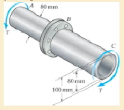
The shaft consists of a solid segment AB and a hollow segment BC, which are rigidly joined by the coupling at B. If the shaft is made from A-36 steel, determine the maximum torque T that can be applied according to the maximum distortion energy theory. Use a factor of safety of 1.5 against yielding.
Expert Solution & Answer
Want to see the full answer?
Check out a sample textbook solution
Students have asked these similar questions
The Am1004-T61 magnesium tube is bonded to the A-36 steel rod. If the allowable shear stresses for the magnesium and steel are (tallow)mg = 45 MPa and (tallow)st = 75 MPa, respectively, determine the maximum allowable torque that can be applied at A. Also, find the corresponding angle of twist of end A.
The composite shaft consists of a mid-section that includes the 1-in.-diameter solid shaft and a tube that is welded to the rigid flanges at A and B. Neglect the thickness of the flanges and determines the angle of twist of end C of the shaft relative to end D. The shaft is subjected to a torque of 800 lb # ft. The material is A-36 steel.
The ends and gears connected to the steel shaft (G = 75 GPa) aresubject to the torques shown. Determine the torsional angle of end B with respect to A.The shaft has a diameter of 40 mm.
Chapter 10 Solutions
Mechanics of Materials (10th Edition)
Ch. 10.3 - Prove that the sum of the normal strains in...Ch. 10.3 - The state of strain at the point on the arm has...Ch. 10.3 - The state of strain at the point on the pin leaf...Ch. 10.3 - The state of strain at the point on the pin leaf...Ch. 10.3 - The state of strain at the point on the leaf of...Ch. 10.3 - Use the strain transformation equations and...Ch. 10.3 - Use the strain transformation equations and...Ch. 10.3 - Use the strain transformation equations to...Ch. 10.3 - Use the strain transformation equations to...Ch. 10.3 - Use the strain- transformation equations to...
Ch. 10.3 - Use the strain transformation equations to...Ch. 10.3 - Determine the equivalent state of strain on an...Ch. 10.3 - Determine the equivalent state of strain which...Ch. 10.3 - Use the strain transformation equations to...Ch. 10.3 - Determine the equivalent state of strain, which...Ch. 10.3 - Solve Prob.103 using Mohrs circle. 103. The state...Ch. 10.3 - using Mohrs circle. 103. The state of strain at...Ch. 10.3 - Solve Prob.105 using Mohrs circle. 105. The state...Ch. 10.3 - Solve Prob.108 using Mohrs circle 108. The state...Ch. 10.3 - using Mohrs circle. 106. The state of strain at a...Ch. 10.5 - The strain at point A on the bracket has...Ch. 10.5 - Determine (a) the principal strains at A, (b) the...Ch. 10.5 - Determine (a) the principal strains at A, in the...Ch. 10.5 - The following readings are obtained for each gage:...Ch. 10.5 - The following readings are obtained for each gage:...Ch. 10.5 - The following readings are obtained for each gage:...Ch. 10.5 - The following readings are obtained from each...Ch. 10.6 - For the case of plane stress, show that Hookes law...Ch. 10.6 - to develop the strain tranformation equations....Ch. 10.6 - Determine the modulus of elasticity and Polssons...Ch. 10.6 - If it is subjected to an axial load of 15 N such...Ch. 10.6 - If it has the original dimensions shown, determine...Ch. 10.6 - If it has the original dimensions shown, determine...Ch. 10.6 - A strain gage having a length of 20 mm Is attached...Ch. 10.6 - Determine the bulk modulus for each of the...Ch. 10.6 - The strain gage is placed on the surface of the...Ch. 10.6 - Determine the associated principal stresses at the...Ch. 10.6 - Determine the applied load P. What is the shear...Ch. 10.6 - If a load of P = 3 kip is applied to the A-36...Ch. 10.6 - The cube of aluminum is subjected to the three...Ch. 10.6 - The principal strains at a point on the aluminum...Ch. 10.6 - A uniform edge load of 500 lb/in. and 350 lb/in....Ch. 10.6 - Prob. 10.45PCh. 10.6 - A single strain gage, placed in the vertical plane...Ch. 10.6 - A single strain gage, placed in the vertical plane...Ch. 10.6 - If the material is graphite for which Eg = 800 ksi...Ch. 10.6 - Determine the normal stresses x and y in the plate...Ch. 10.6 - The steel shaft has a radius of 15 mm. Determine...Ch. 10.6 - Prob. 10.51PCh. 10.6 - The A-36 steel pipe is subjected to the axial...Ch. 10.6 - Air is pumped into the steel thin-walled pressure...Ch. 10.6 - Air is pumped into the steel thin-walled pressure...Ch. 10.6 - Prob. 10.55PCh. 10.6 - The thin-walled cylindrical pressure vessel of...Ch. 10.6 - The thin-walled cylindrical pressure vessel of...Ch. 10.6 - Prob. 10.58PCh. 10.7 - A material is subjected to plane stress. Express...Ch. 10.7 - A material is subjected to plane stress. Express...Ch. 10.7 - The yield stress for a zirconium-magnesium alloy...Ch. 10.7 - Solve Prob. 1061 using the maximum distortion...Ch. 10.7 - If a machine part is made of tool L2 steel and a...Ch. 10.7 - Solve Prob.1063 using the maximum distortion...Ch. 10.7 - Prob. 10.65PCh. 10.7 - If a shaft is made of a material for which y = 75...Ch. 10.7 - Solve Prob.1066 using the maximum shear stress...Ch. 10.7 - If the material is machine steel having a yield...Ch. 10.7 - The short concrete cylinder having a diameter of...Ch. 10.7 - Prob. 10.70PCh. 10.7 - The plate is made of Tobin bronze, which yields at...Ch. 10.7 - The plate is made of Tobin bronze, which yields at...Ch. 10.7 - An aluminum alloy is to be used for a solid drive...Ch. 10.7 - If a machine part is made of titanium (TI-6A1-4V)...Ch. 10.7 - The components of plane stress at a critical point...Ch. 10.7 - The components of plane stress at a critical point...Ch. 10.7 - The 304-stainless-steel cylinder has an inner...Ch. 10.7 - The 304-stainless-steel cylinder has an inner...Ch. 10.7 - If the 2-in diameter shaft is made from brittle...Ch. 10.7 - If the 2-in diameter shaft is made from cast iron...Ch. 10.7 - If Y = 50 ksi, determine the factor of safety for...Ch. 10.7 - Prob. 10.82PCh. 10.7 - If the yield stress for steel is Y = 36 ksi,...Ch. 10.7 - Prob. 10.84PCh. 10.7 - The state of stress acting at a critical point on...Ch. 10.7 - The shaft consists of a solid segment AB and a...Ch. 10.7 - The shaft consists of a solid segment AB and a...Ch. 10.7 - Prob. 10.88PCh. 10.7 - If Y = 50 ksi, determine the factor of safety for...Ch. 10.7 - The gas tank is made from A-36 steel and has an...Ch. 10.7 - The internal loadings at a critical section along...Ch. 10.7 - If the material is machine steel having a yield...Ch. 10.7 - If the material is machine steel having a yield...Ch. 10 - In the case of plane stress, where the in-plane...Ch. 10 - The plate is made of material having a modulus of...Ch. 10 - If the material is machine steel having a yield...Ch. 10 - Determine if yielding has occurred on the basis of...Ch. 10 - The 60 strain rosette is mounted on a beam. The...Ch. 10 - Use the strain transformation equations to...Ch. 10 - If the strain gages a and b at points give...Ch. 10 - Use the strain-transformation equations and...Ch. 10 - Use the strain transformation equations to...Ch. 10 - Specify the orientation of the corresponding...
Knowledge Booster


Learn more about
Need a deep-dive on the concept behind this application? Look no further. Learn more about this topic, mechanical-engineering and related others by exploring similar questions and additional content below.Similar questions
- A flanged bolt coupling has ten (10) steel 25.4 mm diameter boltsevenly tighten around a 415 mm bolt circle. Determine the torquecapacity of the connection if the allowable shearing stress inthe bolt is 50 MN/m2arrow_forwardThe hollow shaft has an outside diameter of 22mm and an inside diameter of 15mm. A torque of 1000N-m is applied in the end of the shift in the shown direction. Calculate the shear stress at point C .arrow_forwardThe composite shaft consists of a mid-section that includes the 1-in.-diameter solid shaft and a tube that is welded to the rigid flanges at A and B. Neglect the thickness of the flanges and determine the angle of twist of end C of the shaft relative to end D.The shaft is subjected to a torque of 800 lb.ft.The material is A-36 steel.arrow_forward
- A solid shaft has a diameter of 25 mm and is subjected to a torque of 200 Nm at one end.Determine the maximum shear stress in the shaft and the angle of twist over 0.8 m length.Given that the Modulus of Rigidity, G = 85GPa.arrow_forwardThe two shafts are made of steel (G=11x106 lb/in2). Each has a diameter of 1 in. , and they are supported by bearings at A, B and C, which allow free rotation. If the support at D is fixed, determine the angle of twist of end A when the torques are applied to the assembly as shown. Torque applied at H of 80 ft lbs, and at G of 40 ft lbs in opposing directions as seen in the figurearrow_forwardA shaft with two segments (one with constant cross-section of 40-mm-diameter, 500-mm--length and one with the tapered cross-section from 40-mm-diameter to 20-mm-diameter, 400-mm-length) is fixed between walls and a torque T is applied at the junction. Determine the angle of twist at B. Shaft is made of 6061-T6 Aluminum.arrow_forward
- A 2in diameter shaft is made of aluminum 2014-T6, and has a torque of 1/2T, -T and 2/3T respectively along its length measured from the free end with the distance of 12 inches between its section. If the factor of safety of 3 is used and the angle of twist is limited such that it does not exceed 0.1 rad. find the maximum allowable tonque T in the shaft in ksiarrow_forwardThe composite shaft consists of a mid-section that includes the 1-in. diameter solid shaft and a tube that is welded to the rigid flanges at A and B. Neglect the thickness of the flanges. The shaft is subjected to a torque of T=950 lb-ft. The material is A-38 steel, G = 11 x 10³ ksi- (Eigure 1) T 1 in. 3 in. 0.25 in. 0.75 ft. B 0.5 ft Determine the angle of twist of end C of the shaft relative to end D.arrow_forwardThe motor A delivers 7500 kW to the shaft at 3600 rev/min, of which 2500 kW is removed by gear B and 5000 kW is removed by gear C. Determine (a) the maximum shear stress in the shaft; and (b) the angle of twist of end D relative to end A. Use G = 83 GPa for steel, and assume that friction at bearing D is negligible. Show complete solution, and the free body diagram.arrow_forward
- The shaft is made from a solid steel section AB and a tubular portion made of steel and having a brass core. If it is fixed to a rigid support at A, and a torque of T = 50 lb.ft is applied to it at C, determine the rotation angle that occurs at C relative to A and compute the maximum shear stress and maximum shear strain in the brass and steel. Take Gst = 11500 ksi, Gbr = 5600 Ksi. 3 ft 0.5 in. B 1 in. T = 50 lb•ftarrow_forwardIf the solid shaft AB to which the valve handle is attached is made of C83400 red brass and has a diameter of 10 mm, determine the maximum couple forces F that can be applied to the handle just before the material starts to fail. Take 7allow = 40 MPa. What is the angle of twist of the handle? The shaft is fixed at A. 150 mm 150 mm 150 mmarrow_forwardThe aluminum shaft, composed of three segments is fastened to rigid supports as A and D. Calculate the maximum shear stress in each segment when the two torques are applied. A 400 N-m 850 N-m L=1.4 m 30 mm diameter B L=2.4 m 50 mm diameter L-1.9 m 30 mm diameterarrow_forward
arrow_back_ios
SEE MORE QUESTIONS
arrow_forward_ios
Recommended textbooks for you
 Elements Of ElectromagneticsMechanical EngineeringISBN:9780190698614Author:Sadiku, Matthew N. O.Publisher:Oxford University Press
 Mechanics of Materials (10th Edition)Mechanical EngineeringISBN:9780134319650Author:Russell C. HibbelerPublisher:PEARSON
 Thermodynamics: An Engineering ApproachMechanical EngineeringISBN:9781259822674Author:Yunus A. Cengel Dr., Michael A. BolesPublisher:McGraw-Hill Education
 Control Systems EngineeringMechanical EngineeringISBN:9781118170519Author:Norman S. NisePublisher:WILEY
 Mechanics of Materials (MindTap Course List)Mechanical EngineeringISBN:9781337093347Author:Barry J. Goodno, James M. GerePublisher:Cengage Learning
 Engineering Mechanics: StaticsMechanical EngineeringISBN:9781118807330Author:James L. Meriam, L. G. Kraige, J. N. BoltonPublisher:WILEY
Elements Of Electromagnetics
Mechanical Engineering
ISBN:9780190698614
Author:Sadiku, Matthew N. O.
Publisher:Oxford University Press
Mechanics of Materials (10th Edition)
Mechanical Engineering
ISBN:9780134319650
Author:Russell C. Hibbeler
Publisher:PEARSON
Thermodynamics: An Engineering Approach
Mechanical Engineering
ISBN:9781259822674
Author:Yunus A. Cengel Dr., Michael A. Boles
Publisher:McGraw-Hill Education
Control Systems Engineering
Mechanical Engineering
ISBN:9781118170519
Author:Norman S. Nise
Publisher:WILEY
Mechanics of Materials (MindTap Course List)
Mechanical Engineering
ISBN:9781337093347
Author:Barry J. Goodno, James M. Gere
Publisher:Cengage Learning
Engineering Mechanics: Statics
Mechanical Engineering
ISBN:9781118807330
Author:James L. Meriam, L. G. Kraige, J. N. Bolton
Publisher:WILEY
Understanding Failure Theories (Tresca, von Mises etc...); Author: The Efficient Engineer;https://www.youtube.com/watch?v=xkbQnBAOFEg;License: Standard youtube license