
Videos
using Mohr’s circle.
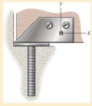
10−6. The state of strain at a point on the bracket has components of εx = 150(10−6), εy = 200(10−6), γxy = −700(10−6). Use the strain transformation equations and determine the equivalent in-plane strains on an element oriented at an angle of θ = 60° counterclockwise from the original position. Sketch the deformed element within the x–y plane due to these strains.
10−7. Solve Prob.10-6 for an element oriented θ = 30° clockwise.
Want to see the full answer?
Check out a sample textbook solution
Chapter 10 Solutions
Mechanics of Materials (10th Edition)
Additional Engineering Textbook Solutions
Fluid Mechanics: Fundamentals and Applications
Engineering Mechanics: Dynamics (14th Edition)
Degarmo's Materials And Processes In Manufacturing
INTERNATIONAL EDITION---Engineering Mechanics: Statics, 14th edition (SI unit)
Vector Mechanics for Engineers: Dynamics
Engineering Mechanics: Statics


- For the state of a plane strain with εx, εy and γxy components: (a) construct Mohr’s circle and (b) determine the equivalent in-plane strains for an element oriented at an angle of 30° clockwise. εx = 255 × 10-6 εy = -320 × 10-6 γxy = -165 × 10-6arrow_forward(b) A differential element on the bracket as shown in Figure Q1 is subjected to plane strain that has the following components: ex = 150µ, ey = 200μ , γχν = -700μ. By using the strain transformation equations, determine:- The equivalent in-plane strains on an element oriented at an angle 0 = 60° counterclockwise from the original position. (ii) Sketch the deformed element within the x' – y' plane due to these strains. (iii) The stresses on the oriented planes in (i) where the value of elasticity, E = 200 GPa and Poisson's ratio, v = 0.32. (iv) Give your comments on those stresses in (iii) in terms of elastic limit/failure if the material's yield strength in tension/compression is 250 MPa and in shear is 90 MPa.arrow_forwardThe state of strain at the point on the leaf of the caster assembly has components of Ex = -400(10-6), y = 860(10-6), and Yxy = 375(10-6). Use the strain transformation equations to determine the equivalent in-plane strains on an element oriented at an angle of 0 = 30° counterclockwise from the original position. Sketch the deformed element due to these strains within the x-y plane.arrow_forward
- The state of strain at a point on the bracket has components of Px = 150(10-6), Py = 200(10-6), gxy = -700(10-6). Use the strain transformation equations and determine the equivalent in-plane strains on an element oriented at an angle of u = 60° counterclockwise from the original position. Sketch the deformed element within the x–y plane due to these strains.arrow_forwardThe state of strain at the point on the leaf of the caster assembly has components of P x = -400(10-6), Py = 860(10-6), and gxy = 375(10-6). Use the strain transformation equations to determine the equivalent in-plane strains on an element oriented at an angle of u = 30 counterclockwise from the original position. Sketch the deformed element due to these strains within the x–y plane.arrow_forwardA strain gauge that is attached to the surface of a stressed componentgives 3 readings (εa = 310, εb = B=150, εc = C=-300). If the strain gauge is of the 60 degreestype (indicating the angle between each of the gauges), construct a Mohr’s StrainCircle. Gauge A is aligned along the x-axis. Using Mohr’s Strain Circle calculate the:(i) principal strains (ε1, ε2) (ii) principal angles (φ1, φ2) (You should measure these anticlockwise from the y-axis)(iii) maximum shear strain in the plane (γmax)arrow_forward
- The strain components Ex, Ey, and Yxy are given for a point in a body subjected to plane strain. Using Mohr's circle, determine the principal strains, the maximum in-plane shear strain, and the absolute maximum shear strain at the point. Show the angle 0p, the principal strain deformations, and the maximum in-plane shear strain distortion in a sketch. Ex = 0 μE, Ey = 310 με, Yxy = 280 μrad. Enter the angle such that -45° ≤ 0,≤ +45° Answer: Ep1 = Ep2 = Ymax in-plane = Yabsolute max. = 0p = με με urad uradarrow_forwardThe state of strain at the point on the gear tooth has components €x = 850(106), €y = 480(106), Yxy = 650(106). Use the strain-transformation equations to determine (a) the in-plane principal strains and (b) the maximum in-plane shear strain and average normal strain. In each case specify the orientation of the element and show how the strains deform the element within the x-y plane.arrow_forwardThe state of strain at the point on the spanner wrench has components of Px = 260(10-6), P y = 320(10-6), and gxy = 180(10-6). Use the strain transformation equations to determine (a) the in-plane principal strains and (b) the maximum in-plane shear strain and average normal strain. In each case specify the orientation of the element and show how the strains deform the element within the x–y plane.arrow_forward
- The state of strain on an element has components εx=−270(10−6)εx=−270(10−6), εy=120(10−6)εy=120(10−6), γxy=130(10−6)γxy=130(10−6). Specify the orientation of the corresponding elements for these states of strain with respect to the original element.-Determine the orientation of principle strains for p1 and p2 -Determine the orientation of maximum in-plane shear strain for s1 and s2arrow_forwardThe state of strain at the point on the arm in Figure Q10 has components ϵx = 200.5 micro-strain, ϵy = 324.4 micro-strain, and γxy = 220.6 micro-strain (1 micro-strain = strain×10-6). Figure 10 Calculate the maximum principal strain. Express your answer in micro-strains. Report your answer to 1 decimal place.arrow_forwardThe strain components for a point in a body subjected to plane strain are εx = -480 με, εy = -750με and γxy = -914 μrad. Using Mohr’s circle, determine the principal strains (εp1 > εp2), the maximum inplane shear strain γip, and the absolute maximum shear strain γmax at the point. Show the angle θp (counterclockwise is positive, clockwise is negative), the principal strain deformations, and the maximum in-plane shear strain distortion in a sketch.arrow_forward
 Elements Of ElectromagneticsMechanical EngineeringISBN:9780190698614Author:Sadiku, Matthew N. O.Publisher:Oxford University Press
 Mechanics of Materials (10th Edition)Mechanical EngineeringISBN:9780134319650Author:Russell C. HibbelerPublisher:PEARSON
 Thermodynamics: An Engineering ApproachMechanical EngineeringISBN:9781259822674Author:Yunus A. Cengel Dr., Michael A. BolesPublisher:McGraw-Hill Education
 Control Systems EngineeringMechanical EngineeringISBN:9781118170519Author:Norman S. NisePublisher:WILEY
 Mechanics of Materials (MindTap Course List)Mechanical EngineeringISBN:9781337093347Author:Barry J. Goodno, James M. GerePublisher:Cengage Learning
 Engineering Mechanics: StaticsMechanical EngineeringISBN:9781118807330Author:James L. Meriam, L. G. Kraige, J. N. BoltonPublisher:WILEY