
Mechanics of Materials (10th Edition)
10th Edition
ISBN: 9780134319650
Author: Russell C. Hibbeler
Publisher: PEARSON
expand_more
expand_more
format_list_bulleted
Videos
Textbook Question
Chapter 10.7, Problem 10.86P
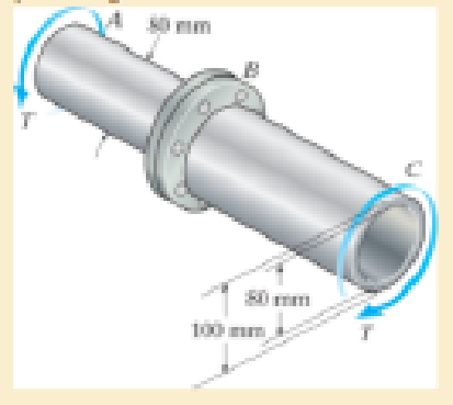
The shaft consists of a solid segment AB and a hollow segment BC, which are rigidly joined by the coupling at B. If the shaft is made from A-36 steel, determine the maximum torque T that can be applied according to the maximum shear stress theory. Use a factor of safety of 1.5 against yielding.
Expert Solution & Answer
Want to see the full answer?
Check out a sample textbook solution
Students have asked these similar questions
The Am1004-T61 magnesium tube is bonded to the A-36 steel rod. If the allowable shear stresses for the magnesium and steel are (tallow)mg = 45 MPa and (tallow)st = 75 MPa, respectively, determine the maximum allowable torque that can be applied at A. Also, find the corresponding angle of twist of end A.
The composite shaft consists of a mid-section that includes the 1-in.-diameter solid shaft and a tube that is welded to the rigid flanges at A and B. Neglect the thickness of the flanges and determines the angle of twist of end C of the shaft relative to end D. The shaft is subjected to a torque of 800 lb # ft. The material is A-36 steel.
A shaft with two segments (one with constant cross-section of 40-mm-diameter, 500-mm--length and one with the tapered cross-section from 40-mm-diameter to 20-mm-diameter, 400-mm-length) is fixed between walls and a torque T is applied at the junction. Determine the angle of twist at B. Shaft is made of 6061-T6 Aluminum.
Chapter 10 Solutions
Mechanics of Materials (10th Edition)
Ch. 10.3 - Prove that the sum of the normal strains in...Ch. 10.3 - The state of strain at the point on the arm has...Ch. 10.3 - The state of strain at the point on the pin leaf...Ch. 10.3 - The state of strain at the point on the pin leaf...Ch. 10.3 - The state of strain at the point on the leaf of...Ch. 10.3 - Use the strain transformation equations and...Ch. 10.3 - Use the strain transformation equations and...Ch. 10.3 - Use the strain transformation equations to...Ch. 10.3 - Use the strain transformation equations to...Ch. 10.3 - Use the strain- transformation equations to...
Ch. 10.3 - Use the strain transformation equations to...Ch. 10.3 - Determine the equivalent state of strain on an...Ch. 10.3 - Determine the equivalent state of strain which...Ch. 10.3 - Use the strain transformation equations to...Ch. 10.3 - Determine the equivalent state of strain, which...Ch. 10.3 - Solve Prob.103 using Mohrs circle. 103. The state...Ch. 10.3 - using Mohrs circle. 103. The state of strain at...Ch. 10.3 - Solve Prob.105 using Mohrs circle. 105. The state...Ch. 10.3 - Solve Prob.108 using Mohrs circle 108. The state...Ch. 10.3 - using Mohrs circle. 106. The state of strain at a...Ch. 10.5 - The strain at point A on the bracket has...Ch. 10.5 - Determine (a) the principal strains at A, (b) the...Ch. 10.5 - Determine (a) the principal strains at A, in the...Ch. 10.5 - The following readings are obtained for each gage:...Ch. 10.5 - The following readings are obtained for each gage:...Ch. 10.5 - The following readings are obtained for each gage:...Ch. 10.5 - The following readings are obtained from each...Ch. 10.6 - For the case of plane stress, show that Hookes law...Ch. 10.6 - to develop the strain tranformation equations....Ch. 10.6 - Determine the modulus of elasticity and Polssons...Ch. 10.6 - If it is subjected to an axial load of 15 N such...Ch. 10.6 - If it has the original dimensions shown, determine...Ch. 10.6 - If it has the original dimensions shown, determine...Ch. 10.6 - A strain gage having a length of 20 mm Is attached...Ch. 10.6 - Determine the bulk modulus for each of the...Ch. 10.6 - The strain gage is placed on the surface of the...Ch. 10.6 - Determine the associated principal stresses at the...Ch. 10.6 - Determine the applied load P. What is the shear...Ch. 10.6 - If a load of P = 3 kip is applied to the A-36...Ch. 10.6 - The cube of aluminum is subjected to the three...Ch. 10.6 - The principal strains at a point on the aluminum...Ch. 10.6 - A uniform edge load of 500 lb/in. and 350 lb/in....Ch. 10.6 - Prob. 10.45PCh. 10.6 - A single strain gage, placed in the vertical plane...Ch. 10.6 - A single strain gage, placed in the vertical plane...Ch. 10.6 - If the material is graphite for which Eg = 800 ksi...Ch. 10.6 - Determine the normal stresses x and y in the plate...Ch. 10.6 - The steel shaft has a radius of 15 mm. Determine...Ch. 10.6 - Prob. 10.51PCh. 10.6 - The A-36 steel pipe is subjected to the axial...Ch. 10.6 - Air is pumped into the steel thin-walled pressure...Ch. 10.6 - Air is pumped into the steel thin-walled pressure...Ch. 10.6 - Prob. 10.55PCh. 10.6 - The thin-walled cylindrical pressure vessel of...Ch. 10.6 - The thin-walled cylindrical pressure vessel of...Ch. 10.6 - Prob. 10.58PCh. 10.7 - A material is subjected to plane stress. Express...Ch. 10.7 - A material is subjected to plane stress. Express...Ch. 10.7 - The yield stress for a zirconium-magnesium alloy...Ch. 10.7 - Solve Prob. 1061 using the maximum distortion...Ch. 10.7 - If a machine part is made of tool L2 steel and a...Ch. 10.7 - Solve Prob.1063 using the maximum distortion...Ch. 10.7 - Prob. 10.65PCh. 10.7 - If a shaft is made of a material for which y = 75...Ch. 10.7 - Solve Prob.1066 using the maximum shear stress...Ch. 10.7 - If the material is machine steel having a yield...Ch. 10.7 - The short concrete cylinder having a diameter of...Ch. 10.7 - Prob. 10.70PCh. 10.7 - The plate is made of Tobin bronze, which yields at...Ch. 10.7 - The plate is made of Tobin bronze, which yields at...Ch. 10.7 - An aluminum alloy is to be used for a solid drive...Ch. 10.7 - If a machine part is made of titanium (TI-6A1-4V)...Ch. 10.7 - The components of plane stress at a critical point...Ch. 10.7 - The components of plane stress at a critical point...Ch. 10.7 - The 304-stainless-steel cylinder has an inner...Ch. 10.7 - The 304-stainless-steel cylinder has an inner...Ch. 10.7 - If the 2-in diameter shaft is made from brittle...Ch. 10.7 - If the 2-in diameter shaft is made from cast iron...Ch. 10.7 - If Y = 50 ksi, determine the factor of safety for...Ch. 10.7 - Prob. 10.82PCh. 10.7 - If the yield stress for steel is Y = 36 ksi,...Ch. 10.7 - Prob. 10.84PCh. 10.7 - The state of stress acting at a critical point on...Ch. 10.7 - The shaft consists of a solid segment AB and a...Ch. 10.7 - The shaft consists of a solid segment AB and a...Ch. 10.7 - Prob. 10.88PCh. 10.7 - If Y = 50 ksi, determine the factor of safety for...Ch. 10.7 - The gas tank is made from A-36 steel and has an...Ch. 10.7 - The internal loadings at a critical section along...Ch. 10.7 - If the material is machine steel having a yield...Ch. 10.7 - If the material is machine steel having a yield...Ch. 10 - In the case of plane stress, where the in-plane...Ch. 10 - The plate is made of material having a modulus of...Ch. 10 - If the material is machine steel having a yield...Ch. 10 - Determine if yielding has occurred on the basis of...Ch. 10 - The 60 strain rosette is mounted on a beam. The...Ch. 10 - Use the strain transformation equations to...Ch. 10 - If the strain gages a and b at points give...Ch. 10 - Use the strain-transformation equations and...Ch. 10 - Use the strain transformation equations to...Ch. 10 - Specify the orientation of the corresponding...
Additional Engineering Textbook Solutions
Find more solutions based on key concepts
6–1C A mechanic claims to have developed a car engine that runs on water instead of gasoline. What is your resp...
Thermodynamics: An Engineering Approach
A nozzle at A discharges water with an initial velocity of 36 ft/s at an angle with the horizontal. Determine ...
Vector Mechanics for Engineers: Dynamics
A number of common substances are
Some of these materials exhibit characteristics of both solid and fluid beha...
Fox and McDonald's Introduction to Fluid Mechanics
23.23 A highly oxidized and uneven round bar is being turned on a lathe. Would you recommend a small or a large...
Manufacturing Engineering & Technology
Three rigid bodies, 2,3, and 4, are connected by four springs as shown in the figure. A horizontal force of 1,0...
Introduction To Finite Element Analysis And Design
Knowledge Booster


Learn more about
Need a deep-dive on the concept behind this application? Look no further. Learn more about this topic, mechanical-engineering and related others by exploring similar questions and additional content below.Similar questions
- If the solid shaft AB to which the valve handle is attached is made of C83400 red brass and has a diameter of 10 mm, determine the maximum couple forces F that can be applied to the handle just before the material starts to fail. Take 7allow = 40 MPa. What is the angle of twist of the handle? The shaft is fixed at A. 150 mm 150 mm 150 mmarrow_forwardA flanged bolt coupling has ten (10) steel 25.4 mm diameter boltsevenly tighten around a 415 mm bolt circle. Determine the torquecapacity of the connection if the allowable shearing stress inthe bolt is 50 MN/m2arrow_forwardThe shaft is made from a solid steel section AB and a tubular portion made of steel and having a brass core. If it is fixed to a rigid support at A, and a torque of T = 50 lb.ft is applied to it at C, determine the rotation angle that occurs at C relative to A and compute the maximum shear stress and maximum shear strain in the brass and steel. Take Gst = 11500 ksi, Gbr = 5600 Ksi. 3 ft 0.5 in. B 1 in. T = 50 lb•ftarrow_forward
- The compound shaft made from the same material consisting of two segments AC and CB is firmly attached to rigid supports. The allowable shear stress in the shaft is limited to 5500 psi. Determine the maximum torque TO that may be applied at C. Calculate also the angular rotation incurred by segment BC. Use G= 12 x 106 psi.arrow_forwardThe hollow shaft has an outside diameter of 22mm and an inside diameter of 15mm. A torque of 1000N-m is applied in the end of the shift in the shown direction. Calculate the shear stress at point C .arrow_forwardA flanged bolt coupling has eight 10-mm diameter steel bolts on 600 mm diameter bolt circle and six 20 mm diameter bolts on 300 mm diameter bolt circle. Determine the maximum torque that can be applied without exceeding the shear stress of 55 MPa for the bolts and for the rods. Use G = 80 GPa.arrow_forward
- The composite shaft consists of a mid-section that includes the 1-in. diameter solid shaft and a tube that is welded to the rigid flanges at A and B. Neglect the thickness of the flanges. The shaft is subjected to a torque of T=950 lb-ft. The material is A-38 steel, G = 11 x 10³ ksi- (Eigure 1) T 1 in. 3 in. 0.25 in. 0.75 ft. B 0.5 ft Determine the angle of twist of end C of the shaft relative to end D.arrow_forwardThe Am1004-T61 magnesium tube is bonded to the A-36 steel rod. If a torque of T = 5 kN # m is applied to end A, determine the maximum shear stress in each material. Sketch the shear stress distribution.arrow_forwardTwo sections of steel drill pipe, joined by boltedflange plates at B, are being tested to assess the adequacyof both the pipes. In the test, the pipe structureis fixed at A, a concentrated torque of 500 kN ? m isapplied at x = 0.5 m, and uniformly distributed torqueintensity t0 = 250 kN . m/m is applied on pipe BC.Both pipes have the same inner diameter d = 200 mm.Pipe AB has thickness tAB =15 mm, while pipe BChas thickness tBC =12 mm. Find the maximum shearstress and maximum twist of the pipe and their locationsalong the pipe. Assume G = 75 GPa.arrow_forward
- The two shafts are made of steel (G=11x106 lb/in2). Each has a diameter of 1 in. , and they are supported by bearings at A, B and C, which allow free rotation. If the support at D is fixed, determine the angle of twist of end A when the torques are applied to the assembly as shown. Torque applied at H of 80 ft lbs, and at G of 40 ft lbs in opposing directions as seen in the figurearrow_forwardThe motor produces a torque of T = 20 N # m on gear A. If gear C is suddenly locked so it does not turn, yet B can freely turn, determine the angle of twist of F with respect to E and F with respect to D of the L2-steel shaft, which hasan inner diameter of 30 mm and an outer diameter of 50 mm. Also, calculate the absolute maximum shear stress in the shaft. The shaft is supported on journal bearings at G at H.arrow_forwardThe ends and gears connected to the steel shaft (G = 75 GPa) aresubject to the torques shown. Determine the torsional angle of end B with respect to A.The shaft has a diameter of 40 mm.arrow_forward
arrow_back_ios
SEE MORE QUESTIONS
arrow_forward_ios
Recommended textbooks for you
 Elements Of ElectromagneticsMechanical EngineeringISBN:9780190698614Author:Sadiku, Matthew N. O.Publisher:Oxford University Press
 Mechanics of Materials (10th Edition)Mechanical EngineeringISBN:9780134319650Author:Russell C. HibbelerPublisher:PEARSON
 Thermodynamics: An Engineering ApproachMechanical EngineeringISBN:9781259822674Author:Yunus A. Cengel Dr., Michael A. BolesPublisher:McGraw-Hill Education
 Control Systems EngineeringMechanical EngineeringISBN:9781118170519Author:Norman S. NisePublisher:WILEY
 Mechanics of Materials (MindTap Course List)Mechanical EngineeringISBN:9781337093347Author:Barry J. Goodno, James M. GerePublisher:Cengage Learning
 Engineering Mechanics: StaticsMechanical EngineeringISBN:9781118807330Author:James L. Meriam, L. G. Kraige, J. N. BoltonPublisher:WILEY
Elements Of Electromagnetics
Mechanical Engineering
ISBN:9780190698614
Author:Sadiku, Matthew N. O.
Publisher:Oxford University Press
Mechanics of Materials (10th Edition)
Mechanical Engineering
ISBN:9780134319650
Author:Russell C. Hibbeler
Publisher:PEARSON
Thermodynamics: An Engineering Approach
Mechanical Engineering
ISBN:9781259822674
Author:Yunus A. Cengel Dr., Michael A. Boles
Publisher:McGraw-Hill Education
Control Systems Engineering
Mechanical Engineering
ISBN:9781118170519
Author:Norman S. Nise
Publisher:WILEY
Mechanics of Materials (MindTap Course List)
Mechanical Engineering
ISBN:9781337093347
Author:Barry J. Goodno, James M. Gere
Publisher:Cengage Learning
Engineering Mechanics: Statics
Mechanical Engineering
ISBN:9781118807330
Author:James L. Meriam, L. G. Kraige, J. N. Bolton
Publisher:WILEY
Understanding Failure Theories (Tresca, von Mises etc...); Author: The Efficient Engineer;https://www.youtube.com/watch?v=xkbQnBAOFEg;License: Standard youtube license