
Electrical Engineering: Principles & Applications (7th Edition)
7th Edition
ISBN: 9780134484143
Author: Allan R. Hambley
Publisher: PEARSON
expand_more
expand_more
format_list_bulleted
Concept explainers
Videos
Textbook Question
Chapter 1, Problem 1.68P
Consider the circuit shown in Figure P1.68.
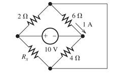
Figure P1.68
- Which elements are in sense?
Expert Solution & Answer

Learn your wayIncludes step-by-step video

schedule09:16
Students have asked these similar questions
2.)What is the difference between Ampere's law and Biot-Savart's law?
For the network shown in figure (3), if the switch is closed for 2usec and then opened for Susec, find mathematical expressions for vi and in of both periods of time and then plot the waveforms of vL and i as a function of time.
SHOW COMPLETE SOLUTIONNNN
Chapter 1 Solutions
Electrical Engineering: Principles & Applications (7th Edition)
Ch. 1 - Broadly speaking, what are the two main objectives...Ch. 1 - Prob. 1.2PCh. 1 - List eight subdivisions of electrical engineering.Ch. 1 - Prob. 1.4PCh. 1 - Prob. 1.5PCh. 1 - In the fluid-flow analogy for electrical circuits,...Ch. 1 - The charge of an electron is 1.601019C . A current...Ch. 1 - The ends of a length of wire are labeled a and b....Ch. 1 - The circuit element shown in Figure P1.9 has v=12V...Ch. 1 - Prob. 1.10P
Ch. 1 - The net charge through a cross section of a...Ch. 1 - The current through a particular circuit element...Ch. 1 - The current through a given circuit element is...Ch. 1 - The net charge through a cross section of a...Ch. 1 - A copper wire has a diameter of 2.05 mm and...Ch. 1 - A certain lead acid storage battery has a mass of...Ch. 1 - A circuit element having terminals a and b has...Ch. 1 - An electron moves through a voltage of 9 V from...Ch. 1 - A typical “deep-cycle” battery (used for electric...Ch. 1 - Define the term passive reference configuration....Ch. 1 - Compute the power for each element shown in Figure...Ch. 1 - The terminals of an electrical device are labeled...Ch. 1 - The terminals of a certain battery are labeled a...Ch. 1 - The element shown in Figure P1.24 I has v(t)=10V...Ch. 1 - The current and voltage of an electrical device...Ch. 1 - Suppose that the cost of electrical energy is...Ch. 1 - Figure P1.27 shows an ammeter (AM) and voltmeter...Ch. 1 - Repeat Problem P1.27 with the meters connected as...Ch. 1 - A certain type of D-cell battery that costs $0.50...Ch. 1 - The electronics aboard a certain sailboat consume...Ch. 1 - What s a node in an electrical circuit? Identify...Ch. 1 - State Kirchhoff’s current law.Ch. 1 - Two electrical elements are connected in series....Ch. 1 - Suppose that in the fluid-flow analogy for an...Ch. 1 - Identify elements that are in series in the...Ch. 1 - Consider the circuit shown in Figure P1.36. Which...Ch. 1 - Use KCL to find the values of ia, ic , and id for...Ch. 1 - Find the values of the other currents in Figure...Ch. 1 - Prob. 1.39PCh. 1 - State Kirchhoff’s voltage law.Ch. 1 - Consider the circuit shown in Figure P1.36. Which...Ch. 1 - Use KVL to solve for the voltages va , vb, and vc...Ch. 1 - Solve for the other voltages shown in Figure P1.43...Ch. 1 - Use KVL and KCL to solve for the labeled currents...Ch. 1 - Identify elements that are in parallel in Figure...Ch. 1 - Points a, b, c, and d appear in a certain circuit....Ch. 1 - In your own words, define an ideal conductor; an...Ch. 1 - Name four types of dependent sources and give the...Ch. 1 - State Ohm’s law, including references.Ch. 1 - Draw a circuit that contains a 5 resistance, a...Ch. 1 - Repeat Problem P1.50, placing all three elements...Ch. 1 - The resistance of a certain copper wire is 0.5. ....Ch. 1 - Draw a circuit that contains a 5 resistor, a 10-V...Ch. 1 - Draw a circuit that contains a 5 resistor, a 10-V...Ch. 1 - A power of 100 W is delivered to a certain...Ch. 1 - The voltage across a 10 resistor is given by...Ch. 1 - The voltage across a 10 resistor is given by...Ch. 1 - A certain wire has a resistance of 0.5 . Find the...Ch. 1 - Plot i versus v to scale for each of the parts of...Ch. 1 - Which of the following are self-contradictory...Ch. 1 - Consider the circuit shown in Figure P1.61. Find...Ch. 1 - Consider the circuit shown in Figure P1.62. Find...Ch. 1 - Consider the circuit shown in Figure P1.63. Find...Ch. 1 - Consider the circuit shown in Figure P1.64. Use...Ch. 1 - Determine the value of Ix in the circuit shown in...Ch. 1 - Consider the circuit shown in Figure P1.66. Figure...Ch. 1 - Prob. 1.67PCh. 1 - Consider the circuit shown in Figure P1.68. Figure...Ch. 1 - Solve for the currents shown in Figure P1.69....Ch. 1 - The circuit shown in Figure P1.70 contains a...Ch. 1 - Determine the value of vx and iy in the circuit...Ch. 1 - A 10-V independent voltage source is in series...Ch. 1 - A 10-V independent voltage source is in parallel...Ch. 1 - Consider the circuit shown in Figure P1.74. Figure...Ch. 1 - The circuit shown in Figure P1.75 contains a...Ch. 1 - For the circuit shown in Figure P1.76, solve for...Ch. 1 - For the circuit shown in Figure P1.77, solve for...Ch. 1 - Match each entry in Table T1.1(a) with the best...Ch. 1 - Prob. 1.2PTCh. 1 - The circuit of Figure T1.3 has I1=3A , I2=1A ,...Ch. 1 - The circuit shown in Figure T1.4 has Vs=12V ,...Ch. 1 - We are given Vs=15V , R=10 , and =0.3S for the...Ch. 1 - We are given i4=2A for the circuit of Figure T1.6....
Additional Engineering Textbook Solutions
Find more solutions based on key concepts
The total resistance RT for the network of Fig. 7.69. is 7.2 k Find the resistance R. Fig. 7.69
Introductory Circuit Analysis (13th Edition)
The switch in the bottom loop of Fig. P6.1 is closed at t = 0 and then opened at a later time t1. What is the d...
Fundamentals of Applied Electromagnetics (7th Edition)
A pilot weighs 150 lb and is traveling at a constant speed of 120 ft/ s. Determine the normal force he exerts o...
Engineering Mechanics: Dynamics (14th Edition)
What parts are included in the vehicle chassis?
Automotive Technology: Principles, Diagnosis, and Service (5th Edition)
The two identical boards are bolted together to form the beam. Determine the maximum spacing s of the bolts to ...
Statics and Mechanics of Materials (5th Edition)
Challenge exercise Implement a method in StockManager to print details of all products with stock levels below ...
Objects First with Java: A Practical Introduction Using BlueJ (6th Edition)
Knowledge Booster


Learn more about
Need a deep-dive on the concept behind this application? Look no further. Learn more about this topic, electrical-engineering and related others by exploring similar questions and additional content below.Similar questions
- show your solutionnnnnnnnarrow_forwardGiven the circuit, solve for: a. using superposition to get the thevenin voltage by R6, what is the contribution of the I1? b. if the load of 250 ohms becomes 100 ohms, what will be the value of Va?arrow_forwardControl Systems Write the state equations of the circuit shown in the figure. Obtain the Vout expression for the values of C=2F and L=3H for R=5 ohms. Obtain the Vout(t) expression by using the sum of residues method when the input voltage is a unit-step function. Comment on the stability of the system. Note:Please explain and explain in detail.arrow_forward
- Basic Electrical EngineeringDraw symbols of electrical components. Note: You may use both IEC and NEMA symbols. - Conductors crossing but not connected- Conductors crossing and connected - DC source other than battery- DC generator- AC voltage source- Ideal current source- Ideal Voltage Source- Current Controlled Current Source- Current Controlled Voltage Source- Voltage Controlled Current Source - Voltage Controlled Voltage Sourcearrow_forwardWhat is Lenz's law and derive its formula.arrow_forwardCould you solve the d and e parts and explain step by step and showing the solutions clearly, please. Thanks a lot.arrow_forward
- Explain why this is the equation for nodal analysis. I need to know how it became negative and positive. Why did Vs1 and Vs2 became negative? Why did Vs3 became positive and so on?arrow_forwardSolve for step by step process with complete solutionsarrow_forwardConsider the circuits shown in the figure. The magnitude of the ratio of the currents, i.e., |I1/I2],arrow_forward
- Consider the electrical circuit shown in the image. There are 4 currents present. The current I enters a note and then branches into three seperate currents, I1, I2, and I3. A) rank the 4 currents according to their magnitude, greatest first. Explain. B)Considering Delta V1, Delta V2, and Delta V3, now rank them according to magnitude. Explain.arrow_forward20 What is countertorque a measure of? PRACTICAL APPLICATIONS ou are working as an electrician in a large steel manufacturing plant, and Y in the of doing preventive maintenance on a large DC you are generator. You have megged both the series and shunt field windings and found that each has over 10 M2 to ground. Your ohmmeter, however, indicates a resistance of 1.5 2 across terminals S, and S,. The ohmmeter indicates a resistance of 225 N between terminals F, and F2. Are these readings normal for this type machine, or is there a likely problem? Explain your answer. processarrow_forwardFigure 2 shows three "LC" circuits, two of them with capacitance capacitors "C" and the three with inductance coils "L", the three circuits are coupled by means of two capacitance capacitors "Cc". The currents that circulate through each mesh are those indicated in the figure: "I1", "I2" and "I3". Using Kirchhoff's law for voltages and taking into account the definition of current I = −dQ / dt, find the system of coupled equations of the system and then find the normal angular frequencies of the system.arrow_forward
arrow_back_ios
SEE MORE QUESTIONS
arrow_forward_ios
Recommended textbooks for you
 Introductory Circuit Analysis (13th Edition)Electrical EngineeringISBN:9780133923605Author:Robert L. BoylestadPublisher:PEARSON
 Delmar's Standard Textbook Of ElectricityElectrical EngineeringISBN:9781337900348Author:Stephen L. HermanPublisher:Cengage Learning
 Programmable Logic ControllersElectrical EngineeringISBN:9780073373843Author:Frank D. PetruzellaPublisher:McGraw-Hill Education
 Fundamentals of Electric CircuitsElectrical EngineeringISBN:9780078028229Author:Charles K Alexander, Matthew SadikuPublisher:McGraw-Hill Education
 Electric Circuits. (11th Edition)Electrical EngineeringISBN:9780134746968Author:James W. Nilsson, Susan RiedelPublisher:PEARSON
 Engineering ElectromagneticsElectrical EngineeringISBN:9780078028151Author:Hayt, William H. (william Hart), Jr, BUCK, John A.Publisher:Mcgraw-hill Education,
Introductory Circuit Analysis (13th Edition)
Electrical Engineering
ISBN:9780133923605
Author:Robert L. Boylestad
Publisher:PEARSON
Delmar's Standard Textbook Of Electricity
Electrical Engineering
ISBN:9781337900348
Author:Stephen L. Herman
Publisher:Cengage Learning
Programmable Logic Controllers
Electrical Engineering
ISBN:9780073373843
Author:Frank D. Petruzella
Publisher:McGraw-Hill Education
Fundamentals of Electric Circuits
Electrical Engineering
ISBN:9780078028229
Author:Charles K Alexander, Matthew Sadiku
Publisher:McGraw-Hill Education
Electric Circuits. (11th Edition)
Electrical Engineering
ISBN:9780134746968
Author:James W. Nilsson, Susan Riedel
Publisher:PEARSON
Engineering Electromagnetics
Electrical Engineering
ISBN:9780078028151
Author:Hayt, William H. (william Hart), Jr, BUCK, John A.
Publisher:Mcgraw-hill Education,
Gradient of a scalar field | Lecture 17 | Vector Calculus for Engineers; Author: Jeffrey Chasnov;https://www.youtube.com/watch?v=W8N8XswNei8;License: Standard Youtube License