
Concept explainers
Videos
The circuit shown in Figure T1.4 has
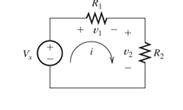
Figure T1.4
a. Find the values of: a.
Want to see the full answer?
Check out a sample textbook solution
Chapter 1 Solutions
Electrical Engineering: Principles & Applications (7th Edition)
Additional Engineering Textbook Solutions
Introductory Circuit Analysis (13th Edition)
Principles Of Electric Circuits
Programmable Logic Controllers
Engineering Electromagnetics
Basic Engineering Circuit Analysis
Fundamentals of Electric Circuits


- Given that: R1=31, R2=25, Is=7.4 A, Vs=7.1 V, Find Vth between the terminals a-b for the circuit shown below R2 Q 6Ω b a R2Q ZR1Q (4 is A VsV Select one: O a. 229.4 Ob. 3.550000 O. 232.950000 O d. none of the above O e. -225.850000arrow_forwardResistors are said to be connected in parallel Select one: a. Circuit elements connected in parallel have the same voltage across their terminals Eion b. All of the answers C. When two circuit elements connect at a single node pair Previous page Next p Jump to... Return to: Generalarrow_forward1. Find the value of Is, V1, 12, 14, V5, Redraw every step. Vi Ri 952 R2 I2 32 R3 24Varrow_forward
- The elements in the circuit shown have the following values: R1 = 1937.97 Q. R2 = 8792.15 Q. Rz R3 = 1441.86 0. It V1 = 8.1 V. 11 = 0.0072 A R. Vo Determine the following: a.) The Thevenin Resistance is, Rth (in ohms): b.) The Thevenin Voltage is, Vth (in volts): c.) The I, output voltage Vo (in volts): Assume R3 to be the load.arrow_forwardR1 R3 V1 R2 RL RL The circuit on the left, as viewed by the load resistor RI , can be reduced via source transformations to a equivalent voltage source Vs in series with a resistor Rg. Given that V1= 17 V. 11= 3 A. R1=4 Ohms, R2= 6 Ohms, and R3= 9 Ohms, determine Ve. (NOTE: Only enter the value for Vs and not Re for your answer to the nearest single digit decimal place). (HINT: Be careful with the polarity of your voltage sources and direction of your current sources when doing your calculations). K< Question 4 of 6 7:54 PM A Moving to another question will save this response. 69°F 9/8/2021 P Type here to search 144arrow_forward2. In the circuit shown in the figure, R1 = 20.0 N, R, = 30.0 N, R3 40.0 2, L = 10.0 H and E = 100 V. What is the current i, in units of ampere att= 0.300 s after the switch is closed. R1 R3 S o 3. R2arrow_forward
- 1/1 By using the experiment of series connection: if the R1=50ohm, R2=100ohm and R3=150ohm.. the voltage drop at R2 is greater than R3 * and less than R1 true O false Oarrow_forwardQ2 (a) () What is the difference between a Wheatstone bridge and a Kelvin bridge? Your explanation should include suitable diagrams and applications. (ii) Figure Q2a(ii) shows an AC bridge and the meter indicates zero reading. Find the equation for R, from the real part of the impedance Figure Q2a(1) (i) Given that the value for the resistors R. R. R. are 100 02, 250 £2 and 300 1, respectively. The capacitors C, and Care 1 uF and 0.5 µF, respectively. Calculate the resistor. Rarrow_forwardb. i.Use Kirchhoff's Voltage Law to mathematically write an expression for the figure below V3 V₁arrow_forward
- i Ii. In. 3 * e 9:Y. 2.7 3.2 For the circuit shown in figure. For the circuit shown in Figure If IB 40 MA , VBB= 6v, RE =I K2, B=80 Rc Rg Vec VBB RE ..The value of IE is . .. 4.24 O 2.024 1.24 3.24 5.24 6.24 IIarrow_forwardFor the circuit shown in the Figure, if R1=8 Q, R2=6 2, and C=0.2 F, and if i = A + Be -/, answer the following two questions: t=0 R1 ww 20-1) V R2 ЗА For i = A + Be t/t, the value of B is: Oa. -0.971 A Ob. -1.518 A Oc. -1.214 A Od. -0.777 A For i = A + Be-t/t , the value of t is: AA A learn.ejust.org wwarrow_forwardUsing the circuit, determine thevenin’s voltage(Vth) and thevenin's resistance(Rth) for load resistor R1. Then solve for I1. Draw all diagrams.arrow_forward
 Introductory Circuit Analysis (13th Edition)Electrical EngineeringISBN:9780133923605Author:Robert L. BoylestadPublisher:PEARSON
 Delmar's Standard Textbook Of ElectricityElectrical EngineeringISBN:9781337900348Author:Stephen L. HermanPublisher:Cengage Learning
 Programmable Logic ControllersElectrical EngineeringISBN:9780073373843Author:Frank D. PetruzellaPublisher:McGraw-Hill Education
 Fundamentals of Electric CircuitsElectrical EngineeringISBN:9780078028229Author:Charles K Alexander, Matthew SadikuPublisher:McGraw-Hill Education
 Electric Circuits. (11th Edition)Electrical EngineeringISBN:9780134746968Author:James W. Nilsson, Susan RiedelPublisher:PEARSON
 Engineering ElectromagneticsElectrical EngineeringISBN:9780078028151Author:Hayt, William H. (william Hart), Jr, BUCK, John A.Publisher:Mcgraw-hill Education,