
Electrical Engineering: Principles & Applications (7th Edition)
7th Edition
ISBN: 9780134484143
Author: Allan R. Hambley
Publisher: PEARSON
expand_more
expand_more
format_list_bulleted
Videos
Textbook Question
Chapter 1, Problem 1.65P
Determine the value of
in the circuit shown in Figure P1.65.
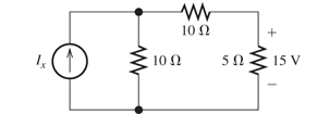
Figure P1.65
Expert Solution & Answer
Want to see the full answer?
Check out a sample textbook solution
Students have asked these similar questions
Determine the value of l x in the circuit shown in Figure P1.65.
a series circuit contains a resistor and an inductor as shown in figure 1.3.14. determine a differential equation for the current i (t) if the resistance is R, the inductance is L, and the impressed voltage is E(t)
Consider the circuit shown in Figure P1.68. a. Which elements are in series?b. Which elements are in parallel? c. Apply Ohm’s and Kirchhoff’s laws to solve for R x.
Chapter 1 Solutions
Electrical Engineering: Principles & Applications (7th Edition)
Ch. 1 - Broadly speaking, what are the two main objectives...Ch. 1 - Prob. 1.2PCh. 1 - List eight subdivisions of electrical engineering.Ch. 1 - Prob. 1.4PCh. 1 - Prob. 1.5PCh. 1 - In the fluid-flow analogy for electrical circuits,...Ch. 1 - The charge of an electron is 1.601019C . A current...Ch. 1 - The ends of a length of wire are labeled a and b....Ch. 1 - The circuit element shown in Figure P1.9 has v=12V...Ch. 1 - Prob. 1.10P
Ch. 1 - The net charge through a cross section of a...Ch. 1 - The current through a particular circuit element...Ch. 1 - The current through a given circuit element is...Ch. 1 - The net charge through a cross section of a...Ch. 1 - A copper wire has a diameter of 2.05 mm and...Ch. 1 - A certain lead acid storage battery has a mass of...Ch. 1 - A circuit element having terminals a and b has...Ch. 1 - An electron moves through a voltage of 9 V from...Ch. 1 - A typical “deep-cycle” battery (used for electric...Ch. 1 - Define the term passive reference configuration....Ch. 1 - Compute the power for each element shown in Figure...Ch. 1 - The terminals of an electrical device are labeled...Ch. 1 - The terminals of a certain battery are labeled a...Ch. 1 - The element shown in Figure P1.24 I has v(t)=10V...Ch. 1 - The current and voltage of an electrical device...Ch. 1 - Suppose that the cost of electrical energy is...Ch. 1 - Figure P1.27 shows an ammeter (AM) and voltmeter...Ch. 1 - Repeat Problem P1.27 with the meters connected as...Ch. 1 - A certain type of D-cell battery that costs $0.50...Ch. 1 - The electronics aboard a certain sailboat consume...Ch. 1 - What s a node in an electrical circuit? Identify...Ch. 1 - State Kirchhoff’s current law.Ch. 1 - Two electrical elements are connected in series....Ch. 1 - Suppose that in the fluid-flow analogy for an...Ch. 1 - Identify elements that are in series in the...Ch. 1 - Consider the circuit shown in Figure P1.36. Which...Ch. 1 - Use KCL to find the values of ia, ic , and id for...Ch. 1 - Find the values of the other currents in Figure...Ch. 1 - Prob. 1.39PCh. 1 - State Kirchhoff’s voltage law.Ch. 1 - Consider the circuit shown in Figure P1.36. Which...Ch. 1 - Use KVL to solve for the voltages va , vb, and vc...Ch. 1 - Solve for the other voltages shown in Figure P1.43...Ch. 1 - Use KVL and KCL to solve for the labeled currents...Ch. 1 - Identify elements that are in parallel in Figure...Ch. 1 - Points a, b, c, and d appear in a certain circuit....Ch. 1 - In your own words, define an ideal conductor; an...Ch. 1 - Name four types of dependent sources and give the...Ch. 1 - State Ohm’s law, including references.Ch. 1 - Draw a circuit that contains a 5 resistance, a...Ch. 1 - Repeat Problem P1.50, placing all three elements...Ch. 1 - The resistance of a certain copper wire is 0.5. ....Ch. 1 - Draw a circuit that contains a 5 resistor, a 10-V...Ch. 1 - Draw a circuit that contains a 5 resistor, a 10-V...Ch. 1 - A power of 100 W is delivered to a certain...Ch. 1 - The voltage across a 10 resistor is given by...Ch. 1 - The voltage across a 10 resistor is given by...Ch. 1 - A certain wire has a resistance of 0.5 . Find the...Ch. 1 - Plot i versus v to scale for each of the parts of...Ch. 1 - Which of the following are self-contradictory...Ch. 1 - Consider the circuit shown in Figure P1.61. Find...Ch. 1 - Consider the circuit shown in Figure P1.62. Find...Ch. 1 - Consider the circuit shown in Figure P1.63. Find...Ch. 1 - Consider the circuit shown in Figure P1.64. Use...Ch. 1 - Determine the value of Ix in the circuit shown in...Ch. 1 - Consider the circuit shown in Figure P1.66. Figure...Ch. 1 - Prob. 1.67PCh. 1 - Consider the circuit shown in Figure P1.68. Figure...Ch. 1 - Solve for the currents shown in Figure P1.69....Ch. 1 - The circuit shown in Figure P1.70 contains a...Ch. 1 - Determine the value of vx and iy in the circuit...Ch. 1 - A 10-V independent voltage source is in series...Ch. 1 - A 10-V independent voltage source is in parallel...Ch. 1 - Consider the circuit shown in Figure P1.74. Figure...Ch. 1 - The circuit shown in Figure P1.75 contains a...Ch. 1 - For the circuit shown in Figure P1.76, solve for...Ch. 1 - For the circuit shown in Figure P1.77, solve for...Ch. 1 - Match each entry in Table T1.1(a) with the best...Ch. 1 - Prob. 1.2PTCh. 1 - The circuit of Figure T1.3 has I1=3A , I2=1A ,...Ch. 1 - The circuit shown in Figure T1.4 has Vs=12V ,...Ch. 1 - We are given Vs=15V , R=10 , and =0.3S for the...Ch. 1 - We are given i4=2A for the circuit of Figure T1.6....
Additional Engineering Textbook Solutions
Find more solutions based on key concepts
With respect to the circuit in Fig. 5.90, (a) employ Thévenin’s theorem to determine the equivalent network see...
Loose Leaf for Engineering Circuit Analysis Format: Loose-leaf
What is the color code for a 365- five-band precision resistor with a tolerance of 5 percent?
ELECTRICITY FOR TRADES (LOOSELEAF)
Analog Voltmeter Design Figure P2-98(a) shows a voltmeter circuit consisting of a D'Arsonval meter, two series ...
ANALYSIS+DESIGN OF LINEAR CIRCUITS(LL)
Write the nodal equations for the network of Fig. 8.137 using the general approach. Find the nodal voltages usi...
Introductory Circuit Analysis (13th Edition)
Three point charges of equal magnitude q, that will yield a zero net electric field at the origin.
Engineering Electromagnetics
How many coulombs do 93.8 1016 electrons represent?
Principles Of Electric Circuits
Knowledge Booster


Learn more about
Need a deep-dive on the concept behind this application? Look no further. Learn more about this topic, electrical-engineering and related others by exploring similar questions and additional content below.Similar questions
- Consider the circuit shown in Figure P1.66. a. Which elements are in series?b. Which elements are in parallel?c. Apply Ohm’s and Kirchhoff’s laws to solve for V x.arrow_forwardFor the circuit shown in Figure P1.77, solve for the current i x. What types of sources are present in this circuit?arrow_forwardIdentify elements that are in parallel a. in Figure P1.37, b. in Figure P1.43, c. in Figure P1.44.arrow_forward
- Solve for the other voltages shown in Figure P1.43 given that v a = 5 V, v b = 7 V, v f = -10 V and v h = 6 V.arrow_forwardPlot i versus v to scale for each of the parts of Figure P1.59.arrow_forwardConsider the circuit shown in Figure P1.61. Find the power for the voltage source and for the current source. Which source is absorbing power?arrow_forward
- aloulated m O1 the value you Up = A cos wt +1o Calaulate maarli)-min(i) =? Use constant voltage drop mad. Don7 to write units. . - 3.7V forgetarrow_forwardConsider the circuit shown in Figure P1.62. Find the current iR flowing through the resistor. Find the power for each element in the circuit. Which elements are absorbing power?arrow_forwarda) Write the expression for the voltage vC after the switch is closed b) Write the expression for the current iC after the switch is closed. Plot the results of parts (a) and (b).arrow_forward
arrow_back_ios
SEE MORE QUESTIONS
arrow_forward_ios
Recommended textbooks for you
 Introductory Circuit Analysis (13th Edition)Electrical EngineeringISBN:9780133923605Author:Robert L. BoylestadPublisher:PEARSON
 Delmar's Standard Textbook Of ElectricityElectrical EngineeringISBN:9781337900348Author:Stephen L. HermanPublisher:Cengage Learning
 Programmable Logic ControllersElectrical EngineeringISBN:9780073373843Author:Frank D. PetruzellaPublisher:McGraw-Hill Education
 Fundamentals of Electric CircuitsElectrical EngineeringISBN:9780078028229Author:Charles K Alexander, Matthew SadikuPublisher:McGraw-Hill Education
 Electric Circuits. (11th Edition)Electrical EngineeringISBN:9780134746968Author:James W. Nilsson, Susan RiedelPublisher:PEARSON
 Engineering ElectromagneticsElectrical EngineeringISBN:9780078028151Author:Hayt, William H. (william Hart), Jr, BUCK, John A.Publisher:Mcgraw-hill Education,
Introductory Circuit Analysis (13th Edition)
Electrical Engineering
ISBN:9780133923605
Author:Robert L. Boylestad
Publisher:PEARSON
Delmar's Standard Textbook Of Electricity
Electrical Engineering
ISBN:9781337900348
Author:Stephen L. Herman
Publisher:Cengage Learning
Programmable Logic Controllers
Electrical Engineering
ISBN:9780073373843
Author:Frank D. Petruzella
Publisher:McGraw-Hill Education
Fundamentals of Electric Circuits
Electrical Engineering
ISBN:9780078028229
Author:Charles K Alexander, Matthew Sadiku
Publisher:McGraw-Hill Education
Electric Circuits. (11th Edition)
Electrical Engineering
ISBN:9780134746968
Author:James W. Nilsson, Susan Riedel
Publisher:PEARSON
Engineering Electromagnetics
Electrical Engineering
ISBN:9780078028151
Author:Hayt, William H. (william Hart), Jr, BUCK, John A.
Publisher:Mcgraw-hill Education,
[2015] Engineering Fundamentals 02: Unit systems. SI unit system [with closed caption]; Author: Yiheng Wang;https://www.youtube.com/watch?v=cryvZJ0KNqk;License: Standard YouTube License, CC-BY