Concept explainers
(a)
The principal mass moment of inertias at the origin.
Answer to Problem B.74P
The principal mass moment of inertias at the origin are
Explanation of Solution
Given information:
The mass per unit length of the steel is
Draw the diagram for the different section of the body.
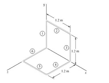
Figure-(1)
Concept used:
Write the expression for the mass of each section.
Here, the mass per unit length is
Write the expression of mass moment of inertia of section 1 about
Write the expression of mass moment of inertia of section 2 about
Write the expression of total mass moment of inertia about
Here, the mass moment of inertia for section 3 about x- axis is
The mass moment of inertia for section 1 is equal to the mass moment of inertia for section 3.
The mass moment of inertia for section 1 is equal to the mass moment of inertia for section 4.
The mass moment of inertia for section 1 is equal to the mass moment of inertia for section 6.
The mass moment of inertia for section 2 is equal to the mass moment of inertia for section 5.
Substitute
Write the expression of total mass moment of inertia about
Here, the mass moment of inertia for section 3 about y- axis is
The mass moment of inertia for section 1 is equal to zero.
The mass moment of inertia for section 4 is equal to the mass moment of inertia for section 5.
The mass moment of inertia for section 2 is equal to the mass moment of inertia for section 6.
Substitute
Write the expression of mass moment of inertia of section 2 about
Write the expression of mass moment of inertia of section 3 about
Write the expression of mass moment of inertia of section 4 about
The figure below illustrates the centroidal axis of a component.
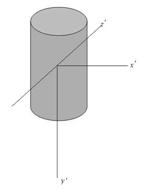
Figure-(2)
From the symmetry in above figure about
Here, the product mass moment of inertia in
From the symmetry in the above figure about
Here, the product mass moment of inertia in
From the symmetry in the above figure about
Here, the product mass moment of inertia in
Write the expression for product of mass moment of inertia in
Here, the product mass moment of inertia is
Write the expression for product mass moment of inertia in
Here, the product mass moment of inertia is
Write the expression for product mass moment of inertia in
Here, the product mass moment of inertia in
Write the expression of mass moment of inertia with respect o origin along the unit vector
Here, the mass moment of inertia with respect to origin along unit vector
Calculation:
Substitute
Substitute
Substitute
Substitute
Substitute
Substitute
Substitute
Substitute
The mass moment of inertia about z- axis and the mass moment of inertia about y- axis is equal due to symmetry.
Hence,
Substitute
Substitute
Substitute
After solving the above equation,
Conclusion:
The principal mass moment of inertias at the origin are
(b)
The principal axis about the origin.
Answer to Problem B.74P
The principal axis about the origin are
Explanation of Solution
Given information:
The mass per unit length of the steel is
Draw the diagram for the different section of the body.
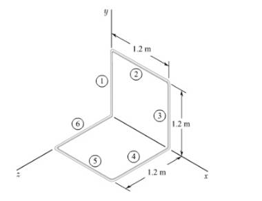
Figure-(1)
Calculation:
The direction cosine is calculated as follows:
Substitute the values from the sub-part (a) in above equations as follows:
After solving above equations,
Direction cosine in x direction is calculated as follows:
Direction cosine in y and z direction are,
So, the direction is calculated as follows:
Again,
The direction cosine is calculated as follows:
Substitute the values from the sub-part (a) in above equations as follows:
After solving above equations,
Direction cosine in x direction is calculated as follows:
Direction cosine in z direction is,
So, the direction is calculated as follows:
Similarly,
The direction cosine is calculated as follows:
Substitute the values from the sub-part (a) in above equations as follows:
After solving above equations,
Direction cosine in x direction is calculated as follows:
Direction cosine in y and z direction are,
So, the direction is calculated as follows:
The sketch is shown below:
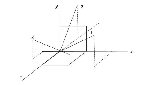
Conclusion:
So, the principal axis about the origin are
Want to see more full solutions like this?
Chapter B Solutions
Vector Mechanics For Engineers
- I want to solve these choicesarrow_forward2. A spur gear made of bronze drives a mid steel pinion with angular velocity ratio of 32: 1. The pressure angle is 14½. It transmits 5 kW at 1800 r.p.m. of pinion. Considering only strength, design the smallest diameter gears and find also necessary face width. The number of teeth should not be less than 15 teeth on either gear. The elastic strength of bronze may be taken as 84 MPa and of steel as 105 MPa. Lewis factor for 14½½ pressure angle may be taken 0.684 0.124 y = No. of teeth as [Ans. m 3 mm; b= 35 mm; Dp = 48 mm; D= 168 mm]arrow_forwardQ2. Determine the safety factors for the bracket rod shown in Figure 2 based on both the distortion-energy theory and the maximum shear theory and compare them. Given: The material is 2024-T4 aluminum with a yield strength of 47 000 psi. The rod length /= 6 in. and arm a = 8 in. The rod outside diameter od 1.5 in., id = 1 in, h=2 in., t=0.5 in., Load F= 1000 lb. Assumptions: The load is static and the assembly is at room temperature. Consider shear due to transverse loading as well as other stresses. (Note: solve in SI units) wall tube Figure 2 armarrow_forward
- The question has been set up with all the cuts needed to accurately derive expressions for V(x) and M(x). Using the cuts free body diagrams set up below, derive expressions for V(x) and M(x). If you use the method of cuts then validate your answers using calculus or vice versa.arrow_forwardIt is required to treat 130 kmol/hr of chloroform-air feed gas mixture that contains 12% chloroform. It is required to remove 93% of chloroform using 150 kmol/hr of solvent that contains 99.6% water and 0.4% chloroform. The cross sectional area of the column is 0.8 m². Calculate the column height using the following data; kx'.a = 1.35 (kmol/m³.s (Ax)), and ky'.a = 0.06 (kmol/m³.s (Ay)), kx/ky = 1.35, and the equilibrium data are: X 0 0.0133 0.033 y 0 0.01 0.0266 0.049 0.064 0.0747 0.0933 0.1053 0.0433 0.06 0.0733 0.111 0.1 0.12 0.14arrow_forward४ B: Find the numerical solution for the 2D equation below and calculate the temperature values for each grid point shown in Fig. 2 (show all steps). (Do only one trail using following initial values and show the final matrix) [T1] T₂ T3 [T] 1 = [0] 0 0 d dx dx) (ka)+4(ka) = dy -20xy, k = 1 + 0.3 T ge L=3cm, 4x= Ay B.Cs.: at x=0=LT=0°C at y=0-L T=10°C Fig. (2)arrow_forward
- : +0 العنوان use only Two rods fins) having same dimensions, one made orass (k = 85 Wm K) and the mer of copper (k = 375 W/m K), having of their ends inserted into a furna. At a section 10.5 cm a way from furnace, the temperature of brass rod 120 Find the distance at which the ame temperature would be reached in the per rod ? both ends are ex osed to the same environment. ns 2.05 ۲/۱ ostrararrow_forwardFor the beam show below, draw A.F.D, S.F.D, B.M.D 6 kN/m 1 M B. 3 M Marrow_forward1. Two long rods of the same diameter-one made of brass (k=85w/m.k) and the other made of copper (k=375 w/m.k) have one of their ends inserted into a furnace (as shown in the following figure). Both rods are exposed to the same environment. At a distance of 105 mm from the furnace, the temperature of the brass rod is 120°C. At what distance from the furnace will the same temperature be reached in the copper rod? Furnace 105 mm T₁ Brass rod ⑪ h Too- x2- Ti Copper rodarrow_forward
- : +0 العنوان use only Two rods fins) having same dimensions, one made orass (k = 85 Wm K) and the mer of copper (k = 375 W/m K), having of their ends inserted into a furna. At a section 10.5 cm a way from furnace, the temperature of brass rod 120 Find the distance at which the ame temperature would be reached in the per rod ? both ends are ex osed to the same environment. ns 2.05 ۲/۱ ostrararrow_forwardمشر on ۲/۱ Two rods (fins) having same dimensions, one made of brass(k=85 m K) and the other of copper (k = 375 W/m K), having one of their ends inserted into a furnace. At a section 10.5 cm a way from the furnace, the temperature brass rod 120°C. Find the distance at which the same temperature would be reached in the copper rod ? both ends are exposed to the same environment. 22.05 ofthearrow_forwardThe composite wall of oven with A= 1m² as in Fig.1 consists of three materials, two of with kA = 20 W/m K and kc = 50 W/m K with thickness, LA=0.3 m, L= 0.15 m and Lc 0.15 m. The inner surface temperature T1=900 K and the outer surface temperature T4 300 K, and an oven air temperature of To=1100 K, h=25 W/m². K. Determine kɛ and the temperatures T2 and T3 also draw the thermal resistance networkarrow_forward
 Elements Of ElectromagneticsMechanical EngineeringISBN:9780190698614Author:Sadiku, Matthew N. O.Publisher:Oxford University Press
 Mechanics of Materials (10th Edition)Mechanical EngineeringISBN:9780134319650Author:Russell C. HibbelerPublisher:PEARSON
 Thermodynamics: An Engineering ApproachMechanical EngineeringISBN:9781259822674Author:Yunus A. Cengel Dr., Michael A. BolesPublisher:McGraw-Hill Education
 Control Systems EngineeringMechanical EngineeringISBN:9781118170519Author:Norman S. NisePublisher:WILEY
 Mechanics of Materials (MindTap Course List)Mechanical EngineeringISBN:9781337093347Author:Barry J. Goodno, James M. GerePublisher:Cengage Learning
 Engineering Mechanics: StaticsMechanical EngineeringISBN:9781118807330Author:James L. Meriam, L. G. Kraige, J. N. BoltonPublisher:WILEY


