
Statics and Mechanics of Materials (5th Edition)
5th Edition
ISBN: 9780134382593
Author: Russell C. Hibbeler
Publisher: PEARSON
expand_more
expand_more
format_list_bulleted
Concept explainers
Videos
Textbook Question
Chapter 9.6, Problem 73P
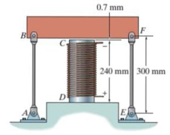
The cylinder CD of the assembly is heated from T1 = 30°C to T2 = 180°C using electrical resistance. Also, the two end rods AB and EF are heated from T1 = 30°C to T2 = 50°C. At the lower temperature T1 the gap between C and the rigid bar is 0.7 mm. Determine the force in rods AB and EF caused by the increase in temperature. Rods AB and EF are made of steel, and each has a cross-sectional area of 125 mm2. CD is made of aluminum and has a cross-sectional area of 375 mm2. Est = 200 GPa, Eal = 70 GPa, αst = 12(10−6)/°C, and αal = 23(10−6)/°C.
Probs. 9-72/73
Expert Solution & Answer
Want to see the full answer?
Check out a sample textbook solution
Students have asked these similar questions
The central bar CD of the assembly is heated from 30 ° C to 180 ° C by means of an electrical resistance. Also the two bars AB and EF are heated from 30 ° C to 50 ° C. At the lower temperature of 30 ° C, the space between C and the rigid bar is 0.7 mm.
Determine the force in bars AB and EF caused by the increase in temperature. Bars AB and EF are made of steel and each has a cross-sectional area of 125 mm ^ 2; CD is aluminum with a cross-sectional area of 375 mm ^ 2. Steel = 200GP; Ealuminum = 70 GPa; alpha steel = 12 X10 ^ -6 (1 / ºC); alpha aluminum = 23 X10 ^ -6 (1 / ° C).
The center rod CD of the assembly is heated from T₁ = 30 °C to T₂ = 165
°C using electrical resistance heating. At the lower temperature T₁ the gap
between C and the rigid bar is 0.7 mm. Rods AB and EF are made of
steel, and each has a cross-sectional area of 125 mm². CD is made of
aluminum and has a cross-sectional area of 375 mm². Est = 200 GPa,
Eal = 70 GPa, and cal = 23 (10-) /°C.
(Figure 1)
Figure
0.7 mm
240 mm
300 mm
Determine the force in the rod AB caused by the increase in temperature.
Express your answer to three significant figures and include the appropriate units.
FAB =
Submit
Part B
FEF=
_O
Submit
μA
Value
Request Answer
Determine the force in the rod EF caused by the increase in temperature.
Express your answer to three significant figures and include the appropriate units.
|μA
Value
Units
Request Answer
?
Units
?
The cylinder CD of the assembly is heated from T1 = 30°C to T2 = 180°C using electrical resistance. At the lower temperature T1 the gap between C and the rigid bar is 0.7 mm. Determine the force in rods AB and EF caused bythe increase in temperature. Rods AB and EF are made of steel, and each has a cross-sectional area of 125 mm2. CD is made of aluminum and has a cross-sectional area of 375 mm2. Est = 200 GPa, Eal = 70 GPa, and aal = 23(10-6)>°C.
Chapter 9 Solutions
Statics and Mechanics of Materials (5th Edition)
Ch. 9.2 - In each case, determine the internal normal force...Ch. 9.2 - Determine the internal normal force between...Ch. 9.2 - The post weighs 8 kN/m. Determine the internal...Ch. 9.2 - The rod is subjected to an external axial force of...Ch. 9.2 - The rigid beam supports the load of 60 kN....Ch. 9.2 - The 20-mm-diameter A-36 steel rod is subjected to...Ch. 9.2 - Prob. 2FPCh. 9.2 - The 30-mm-diameter A992 steel rod is subjected to...Ch. 9.2 - Prob. 4FPCh. 9.2 - Prob. 5FP
Ch. 9.2 - The 20-mm-diameter 2014-T6 aluminum rod is...Ch. 9.2 - The A992 steel rod is subjected to the loading...Ch. 9.2 - The copper shaft is subjected to the axial loads...Ch. 9.2 - The composite shaft, consisting of aluminum,...Ch. 9.2 - The composite shaft, consisting of aluminum,...Ch. 9.2 - The 2014-T6 aluminum rod has a diameter of 30 mm...Ch. 9.2 - The A-36 steel drill shaft of an oil well extends...Ch. 9.2 - The truss is made of three A-36 steel members,...Ch. 9.2 - The truss is made of three A-36 steel members,...Ch. 9.2 - The assembly consists of two 10-mm diameter red...Ch. 9.2 - The assembly consists of two 10-mm diameter red...Ch. 9.2 - The load is supported by the four 304 stainless...Ch. 9.2 - The load is supported by the four 304 stainless...Ch. 9.2 - The rigid bur is supported by the pin-connected...Ch. 9.2 - The post is made of Douglas fir and has a diameter...Ch. 9.2 - The post is made of Douglas fir and has a diameter...Ch. 9.2 - The coupling rod is subjected to a force of 5 kip....Ch. 9.2 - Prob. 17PCh. 9.2 - The linkage is made of three pin-connected A992...Ch. 9.2 - The linkage is made of three pin-connected A992...Ch. 9.2 - The assembly consists of three titanium...Ch. 9.2 - The rigid beam is supported at its ends by two...Ch. 9.2 - Prob. 22PCh. 9.2 - The steel bar has the original dimensions shown in...Ch. 9.2 - Determine the relative displacement of one end of...Ch. 9.2 - Prob. 25PCh. 9.2 - The truss consists of three members, each made...Ch. 9.2 - Prob. 27PCh. 9.2 - The observation cage C has a weight of 250 kip and...Ch. 9.2 - Determine the elongation of the aluminum strap...Ch. 9.2 - The ball is truncated at its ends and is used to...Ch. 9.5 - The column is constructed from high-strength...Ch. 9.5 - The column is constructed from high-strength...Ch. 9.5 - The A-36 steel pipe has a 6061-T6 aluminum core....Ch. 9.5 - If column AB is made from high strength precast...Ch. 9.5 - If column AB is made from high strength precast...Ch. 9.5 - Determine the support reactions at the rigid...Ch. 9.5 - If the supports at A and C are flexible and have a...Ch. 9.5 - The load of 2000 lb is to be supported by the two...Ch. 9.5 - The load of 2000 lb is to be supported by the two...Ch. 9.5 - The A-36 steel pipe has an outer radius of 20 mm...Ch. 9.5 - The 10-mm-diameter steel bolt is surrounded by a...Ch. 9.5 - The 10-mm-diametcr steel bolt is surrounded by a...Ch. 9.5 - The assembly consists of two red brass C83400...Ch. 9.5 - The rigid beam is supported by the three suspender...Ch. 9.5 - Prob. 45PCh. 9.5 - If the gap between C and the rigid wall at D is...Ch. 9.5 - The support consists of a solid red brass C83400...Ch. 9.5 - The specimen represents a filament-reinforced...Ch. 9.5 - The rigid bar is pinned at A and supported by two...Ch. 9.5 - The rigid bar is pinned at A and supported by two...Ch. 9.5 - The rigid bar is pinned at A and supported by two...Ch. 9.5 - The rigid bar is pinned at A and supported by two...Ch. 9.5 - The 2014-T6 aluminum rod AC is reinforced with the...Ch. 9.5 - The 2014-T6 aluminum rod AC is reinforced with the...Ch. 9.5 - The three suspender bars are made of A992 steel...Ch. 9.6 - The C83400-red-brass rod AB and 2014-T6-aluminum...Ch. 9.6 - The assembly has the diameters and material...Ch. 9.6 - The rod is made of A992 steel and has a diameter...Ch. 9.6 - The two cylindrical rod segments are fixed to the...Ch. 9.6 - The two cylindrical rod segments are fixed to the...Ch. 9.6 - Prob. 61PCh. 9.6 - The bronze C86100 pipe has an inner radius of 0.5...Ch. 9.6 - The 40-ft-long A-36 steel rails on a train track...Ch. 9.6 - The device is used to measure a change in...Ch. 9.6 - Prob. 65PCh. 9.6 - Prob. 66PCh. 9.6 - Prob. 67PCh. 9.6 - When the temperature is at 30C, the A-36 steel...Ch. 9.6 - The 50-mm-diameter cylinder is made from Am...Ch. 9.6 - The 50-mm-diametcr cylinder is made from Am...Ch. 9.6 - Prob. 71PCh. 9.6 - The cylinder CD of the assembly is heated from T1...Ch. 9.6 - The cylinder CD of the assembly is heated from T1...Ch. 9.6 - Prob. 74PCh. 9 - The assembly consists of two A992 steel bolts AB...Ch. 9 - The assembly shown consists of two A992 steel...Ch. 9 - The rods each have the same 25-mm diameter and...Ch. 9 - Two A992 steel pipes, each having a...Ch. 9 - The 2014-T6 aluminum rod has a diameter of 0.5 in....Ch. 9 - The 2014-T6 aluminum rod has a diameter of 0.5 in....Ch. 9 - The rigid link is supported by a pin at A and two...Ch. 9 - The joint is made from three A992 steel plates...
Knowledge Booster


Learn more about
Need a deep-dive on the concept behind this application? Look no further. Learn more about this topic, mechanical-engineering and related others by exploring similar questions and additional content below.Similar questions
- 2. The bar has a cross-sectional area A, length L, modulus of elasticity E, and coefficient of thermal expansion a. The temperature of the bar changes uniformly along its length from TA at A to TB at B so that at any point x along the bar T = TA + x(TB – TA)/L. Determine the force the bar exerts on the rigid walls. Initially no axial force is in the bar and the bar has a temperature of TA. A B TA TBarrow_forwardThe 40ft long A-36 steel rails on a train track are laid with a small gap between them to allow for the thermal expansion. Determine the required gap & so that the rails just touch one another when the temperature is increased from T₁=20° F to T₂=90°F. Using this gap, what would be the axial force in the rails if the temperature were to rise to T3=110°F? The cross-sectional area of each rail is 5.10 in²arrow_forwardThe inner ring A has an inner radius r1 and outer radius r2. The outer ring B has an inner radius r3 and an outer radius r4, and r2 7 r3. If the outer ring is heated and then fitted over the inner ring, determine the pressure between the two rings when ring B reaches the temperature of the inner ring. The material has a modulus of elasticity of E and a coefficient of thermal expansion of a.arrow_forward
- 4-69. Three bars each made of different materials are connected together and placed between two walls when the temperature is T₁ = 12°C. Determine the force exerted on the (rigid) supports when the temperature becomes T₂ = 18°C. The material properties and cross-sectional area of each bar are given in the figure. Steel Brass dEst = 200 GPa Ebr = 100 GPa bast=12(10-6)/°C abr 21(106)/C α = = Aut= 200 mm² Abr = 450 mm² pha2kn 300 mm- 4kn -200 mm- Prob. 4-69 Copper Ecu = 120 GPa-44 17(10-6)/°C Acu = 515 mm² 100 mmarrow_forwardThe wires AB and AC are made of steel, and wire AD is made of copper. Before the 150-lb force is applied, AB and AC are each 60 in. long and AD is 40 in. long. If the temperature is increased by 80 F, determine the force in each wire needed to support the load. Each wire has a cross-sectionalarea of 0.0123 in2. Take Est = 29(10 3) ksi, Ecu = 17(10 3) ksi, fast = 8(10 6)> F, acu = 9.60(10 -6)> F.arrow_forwardThe wires AB and AC are made of steel, and wire AD is made of aluminum. Before the 300 kN force is applied, AB and AC are each 150 mm. long and AD is 100 mm. long. If the temperature is increased by 30°C, determine the force in each wire needed to support the load. Take Est = 200 GPa, Eal = 70 GPa, st = 12 (10") / °C, aal = 23 (10") / °C. Each wire has a cross-sectional area of 0.02 mm². B 100 mm 45° 45° 150 mm 150 mm A 300 kNarrow_forward
- The rod is made of A-36 steel and has a diameter of 0.25in. If the rod is 4ft long when the springs are compressed 0.5in and the temperature of the rod is T=40°F, determine the force in the rod when its temperature is T=160°F. k= 1000 lb/in. ww 4 ft k = 1000 lb/in. WWarrow_forwardThe stepped rod shown in the figure is made of Al 2014-T6 aluminum alloy. At temperature T1 = 20°C, there is a gap of 0.2 mm between point A and the rigid wall. If the temperature is increased to T2-50°C and an axial compressive force of P= 20 kN is applied at point B, determine the support reactions at points A and C. 80 mm B C A 20 kN 120 mm 400 mm 600 mm 0,2 mmarrow_forwardThe 58-mm-diameter cylinder is made from Am 1004-T61 magnesium and is placed the clamp when the temperature is T₁ = 20°C. (Figure 1) Figure 100 mm 150 mm Part A If the 304-stainless-steel carriage bolts of the clamp each have a diameter of 9 mm, and they hold the cylinder snug with negligible force against the rigid jaws, determine the force in the cylinder when the temperature rises to T₂ = 130°C. Express your answer to three significant figures and include the appropriate units. F = 2.37 Submit μÀ ^ Provide Feedback KN WX Previous Answers Request Answer ? X Incorrect; Try Again; 3 attempts remaining Next >arrow_forward
- 3) The plug has a diameter of 30 mm and fits with a rigid sleeve having an inner diameter of 32 mm. Both the plug and the sleeve are 50 mm long. Determine the axial pressure P that must be applied to the top of the plug to cause it to contact the sides of the sleeve. Also, how far must the plug be compressed downward to do this? The plug is made from a material for which E = 5 MPa, v = 0.45. Parrow_forward3. The A-36 steel rod has a diameter of 50 mm and is lightly attached to the rigid supports at A and B when T = 80°C. If the temperature becomes T2 = 20°C and an axial force of P = 200 kN is applied to its center, determine the reactions at A and B. A B -0.5 m 0.5 marrow_forwardThe 58-mm-diameter cylinder is made from Am 1004- T61 magnesium and is placed in the clamp when the temperature is T₁ = 20°C. (Figure 1) Figure III 100 mm < 1 of 1 150 mm Part A If the 304-stainless-steel carriage bolts of the clamp each have a diameter of 9 mm, and they hold the cylinder snug with negligible force against the rigid jaws, determine the force in the cylinder when the temperature rises to T₂ = 130°C. Express your answer to three significant figures and include the appropriate units. F = Submit A Value Provide Feedback μA Request Answer Units www ? Nexarrow_forward
arrow_back_ios
SEE MORE QUESTIONS
arrow_forward_ios
Recommended textbooks for you
 Elements Of ElectromagneticsMechanical EngineeringISBN:9780190698614Author:Sadiku, Matthew N. O.Publisher:Oxford University Press
 Mechanics of Materials (10th Edition)Mechanical EngineeringISBN:9780134319650Author:Russell C. HibbelerPublisher:PEARSON
 Thermodynamics: An Engineering ApproachMechanical EngineeringISBN:9781259822674Author:Yunus A. Cengel Dr., Michael A. BolesPublisher:McGraw-Hill Education
 Control Systems EngineeringMechanical EngineeringISBN:9781118170519Author:Norman S. NisePublisher:WILEY
 Mechanics of Materials (MindTap Course List)Mechanical EngineeringISBN:9781337093347Author:Barry J. Goodno, James M. GerePublisher:Cengage Learning
 Engineering Mechanics: StaticsMechanical EngineeringISBN:9781118807330Author:James L. Meriam, L. G. Kraige, J. N. BoltonPublisher:WILEY
Elements Of Electromagnetics
Mechanical Engineering
ISBN:9780190698614
Author:Sadiku, Matthew N. O.
Publisher:Oxford University Press
Mechanics of Materials (10th Edition)
Mechanical Engineering
ISBN:9780134319650
Author:Russell C. Hibbeler
Publisher:PEARSON
Thermodynamics: An Engineering Approach
Mechanical Engineering
ISBN:9781259822674
Author:Yunus A. Cengel Dr., Michael A. Boles
Publisher:McGraw-Hill Education
Control Systems Engineering
Mechanical Engineering
ISBN:9781118170519
Author:Norman S. Nise
Publisher:WILEY
Mechanics of Materials (MindTap Course List)
Mechanical Engineering
ISBN:9781337093347
Author:Barry J. Goodno, James M. Gere
Publisher:Cengage Learning
Engineering Mechanics: Statics
Mechanical Engineering
ISBN:9781118807330
Author:James L. Meriam, L. G. Kraige, J. N. Bolton
Publisher:WILEY
Understanding Conduction and the Heat Equation; Author: The Efficient Engineer;https://www.youtube.com/watch?v=6jQsLAqrZGQ;License: Standard youtube license