
Statics and Mechanics of Materials (5th Edition)
5th Edition
ISBN: 9780134382593
Author: Russell C. Hibbeler
Publisher: PEARSON
expand_more
expand_more
format_list_bulleted
Videos
Textbook Question
Chapter 9.2, Problem 4P
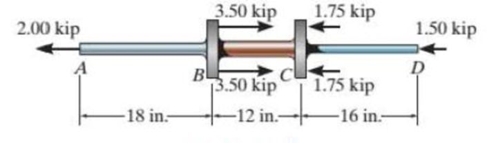
The composite shaft, consisting of aluminum, copper, and steel sections, is subjected to the loading shown. Determine the displacement of B with respect to C. The cross-sectional area and modulus of elasticity for each section are shown in the figure. Neglect the size of the collars at B and C.
| Aluminum | Copper | Steel |
| Eal = 10(103) ksi | Ecu = 18(103) ksi | Est =29(103) ksi |
| AAB = 0.09 in2 | ABC = 0.12 in2 | ACD = 0.06 in2 |
Probs. 9-3/4
Expert Solution & Answer
Want to see the full answer?
Check out a sample textbook solution
Students have asked these similar questions
The composite shaft, consisting of aluminum, copper, and steel sections, is subjected to the loading shown. Determine the displacement of B with respect to C. The cross-sectional area and modulus of elasticity for eachsection are shown in the figure. Neglect the size of the collars at B and C.
The
The composite shaft, consisting of aluminum, copper, and steel sections, is
subjected to the loading shown. The cross-sectional area and modulus of elasticity for each
orl section are shown in the figure. The material of section AB, BC, and CD is aluminum, copper,
and steel, respectively. Neglect the size of the collars at B and C. Determine (a) the
displacement of end A with respect to end D, (b) the displacement of end B with respect to end
C, and (c) the normal stress in each section.
Aluminum
Соpper
Steel
Ea = 10(103) ksi
AAB= 0.09 in?
Ecu = 18(10') ksi
ABC = 0.12 in?
E = 29(103) ksi
Acd = 0.06 in²
%3D
3.50 kip
1.75 kip
2.00 kip
1.50 kip
A
B
3.50 kip
1.75 kip
-18 in.-
-12 in.-
-16 in.-
The rigid beam supports the load of 50 kN as in the figure below. Determine the displacement at B. Neglect the weight
of the structure. Use E = 73 GPa. The rod BC has diameter of 50 mm.
50 kN
-2 m
4 m
A
В
2 m
3 m
D
Chapter 9 Solutions
Statics and Mechanics of Materials (5th Edition)
Ch. 9.2 - In each case, determine the internal normal force...Ch. 9.2 - Determine the internal normal force between...Ch. 9.2 - The post weighs 8 kN/m. Determine the internal...Ch. 9.2 - The rod is subjected to an external axial force of...Ch. 9.2 - The rigid beam supports the load of 60 kN....Ch. 9.2 - The 20-mm-diameter A-36 steel rod is subjected to...Ch. 9.2 - Prob. 2FPCh. 9.2 - The 30-mm-diameter A992 steel rod is subjected to...Ch. 9.2 - Prob. 4FPCh. 9.2 - Prob. 5FP
Ch. 9.2 - The 20-mm-diameter 2014-T6 aluminum rod is...Ch. 9.2 - The A992 steel rod is subjected to the loading...Ch. 9.2 - The copper shaft is subjected to the axial loads...Ch. 9.2 - The composite shaft, consisting of aluminum,...Ch. 9.2 - The composite shaft, consisting of aluminum,...Ch. 9.2 - The 2014-T6 aluminum rod has a diameter of 30 mm...Ch. 9.2 - The A-36 steel drill shaft of an oil well extends...Ch. 9.2 - The truss is made of three A-36 steel members,...Ch. 9.2 - The truss is made of three A-36 steel members,...Ch. 9.2 - The assembly consists of two 10-mm diameter red...Ch. 9.2 - The assembly consists of two 10-mm diameter red...Ch. 9.2 - The load is supported by the four 304 stainless...Ch. 9.2 - The load is supported by the four 304 stainless...Ch. 9.2 - The rigid bur is supported by the pin-connected...Ch. 9.2 - The post is made of Douglas fir and has a diameter...Ch. 9.2 - The post is made of Douglas fir and has a diameter...Ch. 9.2 - The coupling rod is subjected to a force of 5 kip....Ch. 9.2 - Prob. 17PCh. 9.2 - The linkage is made of three pin-connected A992...Ch. 9.2 - The linkage is made of three pin-connected A992...Ch. 9.2 - The assembly consists of three titanium...Ch. 9.2 - The rigid beam is supported at its ends by two...Ch. 9.2 - Prob. 22PCh. 9.2 - The steel bar has the original dimensions shown in...Ch. 9.2 - Determine the relative displacement of one end of...Ch. 9.2 - Prob. 25PCh. 9.2 - The truss consists of three members, each made...Ch. 9.2 - Prob. 27PCh. 9.2 - The observation cage C has a weight of 250 kip and...Ch. 9.2 - Determine the elongation of the aluminum strap...Ch. 9.2 - The ball is truncated at its ends and is used to...Ch. 9.5 - The column is constructed from high-strength...Ch. 9.5 - The column is constructed from high-strength...Ch. 9.5 - The A-36 steel pipe has a 6061-T6 aluminum core....Ch. 9.5 - If column AB is made from high strength precast...Ch. 9.5 - If column AB is made from high strength precast...Ch. 9.5 - Determine the support reactions at the rigid...Ch. 9.5 - If the supports at A and C are flexible and have a...Ch. 9.5 - The load of 2000 lb is to be supported by the two...Ch. 9.5 - The load of 2000 lb is to be supported by the two...Ch. 9.5 - The A-36 steel pipe has an outer radius of 20 mm...Ch. 9.5 - The 10-mm-diameter steel bolt is surrounded by a...Ch. 9.5 - The 10-mm-diametcr steel bolt is surrounded by a...Ch. 9.5 - The assembly consists of two red brass C83400...Ch. 9.5 - The rigid beam is supported by the three suspender...Ch. 9.5 - Prob. 45PCh. 9.5 - If the gap between C and the rigid wall at D is...Ch. 9.5 - The support consists of a solid red brass C83400...Ch. 9.5 - The specimen represents a filament-reinforced...Ch. 9.5 - The rigid bar is pinned at A and supported by two...Ch. 9.5 - The rigid bar is pinned at A and supported by two...Ch. 9.5 - The rigid bar is pinned at A and supported by two...Ch. 9.5 - The rigid bar is pinned at A and supported by two...Ch. 9.5 - The 2014-T6 aluminum rod AC is reinforced with the...Ch. 9.5 - The 2014-T6 aluminum rod AC is reinforced with the...Ch. 9.5 - The three suspender bars are made of A992 steel...Ch. 9.6 - The C83400-red-brass rod AB and 2014-T6-aluminum...Ch. 9.6 - The assembly has the diameters and material...Ch. 9.6 - The rod is made of A992 steel and has a diameter...Ch. 9.6 - The two cylindrical rod segments are fixed to the...Ch. 9.6 - The two cylindrical rod segments are fixed to the...Ch. 9.6 - Prob. 61PCh. 9.6 - The bronze C86100 pipe has an inner radius of 0.5...Ch. 9.6 - The 40-ft-long A-36 steel rails on a train track...Ch. 9.6 - The device is used to measure a change in...Ch. 9.6 - Prob. 65PCh. 9.6 - Prob. 66PCh. 9.6 - Prob. 67PCh. 9.6 - When the temperature is at 30C, the A-36 steel...Ch. 9.6 - The 50-mm-diameter cylinder is made from Am...Ch. 9.6 - The 50-mm-diametcr cylinder is made from Am...Ch. 9.6 - Prob. 71PCh. 9.6 - The cylinder CD of the assembly is heated from T1...Ch. 9.6 - The cylinder CD of the assembly is heated from T1...Ch. 9.6 - Prob. 74PCh. 9 - The assembly consists of two A992 steel bolts AB...Ch. 9 - The assembly shown consists of two A992 steel...Ch. 9 - The rods each have the same 25-mm diameter and...Ch. 9 - Two A992 steel pipes, each having a...Ch. 9 - The 2014-T6 aluminum rod has a diameter of 0.5 in....Ch. 9 - The 2014-T6 aluminum rod has a diameter of 0.5 in....Ch. 9 - The rigid link is supported by a pin at A and two...Ch. 9 - The joint is made from three A992 steel plates...
Knowledge Booster


Learn more about
Need a deep-dive on the concept behind this application? Look no further. Learn more about this topic, mechanical-engineering and related others by exploring similar questions and additional content below.Similar questions
- Solve the preceding problem (W 250 × 44.8) if the resultant force P equals 110 kN and E = 200 GPa.arrow_forwardThe Z-section of Example D-7 is subjected to M = 5 kN · m, as shown. Determine the orientation of the neutral axis and calculate the maximum tensile stress c1and maximum compressive stress ocin the beam. Use the following numerical data: height; = 200 mm, width ft = 90 mm, constant thickness a = 15 mm, and B = 19.2e. Use = 32.6 × 106 mm4 and I2= 2.4 × 10e mm4 from Example D-7arrow_forwardA thin-walled rectangular tube has uniform thickness t and dimensions a x b to the median line of the cross section (see figure). How does the shear stress in the tube vary with the ratio = a/b if the total length Lmof the median line of the cross section and the torque T remain constant? From your results, show that the shear stress is smallest when the tube is square (ß = 1).arrow_forward
- The composite shaft, consisting of aluminum, copper, and steel sections, is subjected to the loading shown. The cross-sectional areas of sections AB, BC, and CD are AAB = 0.09 in², ABC = 0.15 in², and Acp = 0.05 in², respectively. The modulus of elasticity for each section are shown in the figure. Neglect the size of the collars at B and C. (Figure 1) Figure Aluminum Eal = 10(10³) ksi 2.00 kip -18 in- Copper Ecu = 18(10³) ksi 3.50 kip 13.50 kip -12 in- Steel Est = 29(10³) ksi 1.75 kip 1.75 kip -16 in- 1.50 kip 1 of 1 Part A Determine the normal stress in section AB. Express your answer to three significant figures and include the appropriate units. Enter negative value in the case of compression and positive value in the case of tension. Part B Determine the normal stress in section BC. Express your answer to three significant figures and include the appropriate units. Enter negative value in the case of compression and positive value in the case of tension. OBC = Submit Part C OCD =…arrow_forwardurses This course EHide blocks OP=294 N O P = 235 N Let's consider a rod having a solid circular cross-section with diameter of 5 mm and it is made of a material having a Young's modulus E = 120 Gpa and a Poisson's ratio of 0.33. If a tensile force Fis subjected to that rod cross-section, the diameter becomes 4.998 mm. determine the applied force F. Select one: O a. F= 3427 N O b. F = 8568 N O C.F= 2285 N O d. F= 7140 N O e. F = 5712 N O f.F= 2856 N Finish attempt ...arrow_forwardThe copper shaft is subjected to the axial loads shown. Determine the displacement of end A with respect to end D if the diameters of each segment are dAB = 29 mm, dBc = 54 mm, and dcD = 14 mm. Take Ecu = 125 GPa 36 kN 2 m- 22.5 kN A 22.5 kN B -3.75 m- 2.5 m- 9 kN C 9 kN D 27 kN The displacement of end A with respect to end D is mm Note: Please enter your answer with three significant digits after the decimal point.arrow_forward
- 1. The steel shaft carries the axial loads as shown in the figure below. Determine the change in overall length of the shaft caused by these loads given that P = 3100 Ib. The cross-sectional area for each segment is shown in the figure. Use E = 29 X 10° psi for steel. %3D A = 0.75 in.² ЗР A = 1.0 in.² A = 0.5 in.? 2P -P 4P e-3 ft- - 5 ft 4 ft→arrow_forwardQ / The hollow shaft has 50 mm and 40 mm outer and inner diameters respectively, and is rigid support at its ends A and B as shown in figure. If the torque (1.8 kN.m) is subjected to the shaft at point C, determine the maximum shear stress in element AC and CB as well find the angle of twist at point C. known the modulus of elasticity is 200 Gpa and Poisson's ratio is 0.3arrow_forwardSteel bar in shape, AAB 600 mm and ABc = DACD3D 1200 mm2 are made of two stages. Determine the displacement at end A in (mm). E = 200 GPaarrow_forward
- the cröss-stCtions e-e and f-f, respectively, when a torque T = 800 Nm is applied at point B. Take the shear modulus G= 80 GPa. Qier te cruhe The stepped shaft shown below is rigidly attached at both ends. The shaft segments AC and CD have (a) Find the reactions at both ends. (b) Determine the shear stress developed at points K and L on a cross-section taken from the shaft between points B and C. (c) Find the angle of twist at point C. 30 mm T=800 N.m 20uun 50 mm Activate Windou Section ffSings 200 mm 400 mm 300 mm Section e-earrow_forwardDetermine the nodal displacements at node 1, node 2, and node 3 as shown in the figure. One end of the bar assembly is applied with force and at the other end is fixed. The length of each element is 500 mm. The modulus of elasticity and area of the cross-section is given, E, = 200 GPa and A =125 mm² for element 1 and E, =100 GPa and A, = 125 mm? element 2. 1 2 2 3 50 kN 500 mm 500 mm (А) и, — 0, и, = 0,u, =3 mm,uz = 9 mm (B) и, — 0, и, = 2 mm,u, =6 mm (С) и, = 0,u, =1 mm, u, = 3 mm (D) u, = 0,u, = 0.5 mm,u, =3 mmarrow_forwardA cable is enacting a force, F, on a built-in hook at an angle 9 as shown in the figure. Determine the displacement of the point at which the force acts, in the direction of the cable if the shaft of the hook has a length L, radius r and elastic modulus E. Ignore the deformation of the circular hook. If E= 200 GPa, F = 50 kN, 0 = 25°, L = 1 m, r- 100 mm: Answer: 8 = 0.196 mmarrow_forward
arrow_back_ios
SEE MORE QUESTIONS
arrow_forward_ios
Recommended textbooks for you
 Mechanics of Materials (MindTap Course List)Mechanical EngineeringISBN:9781337093347Author:Barry J. Goodno, James M. GerePublisher:Cengage Learning
Mechanics of Materials (MindTap Course List)
Mechanical Engineering
ISBN:9781337093347
Author:Barry J. Goodno, James M. Gere
Publisher:Cengage Learning
Everything About TRANSVERSE SHEAR in 10 Minutes!! - Mechanics of Materials; Author: Less Boring Lectures;https://www.youtube.com/watch?v=4x0E9yvzfCM;License: Standard Youtube License