
Electrical Engineering: Principles & Applications (7th Edition)
7th Edition
ISBN: 9780134484143
Author: Allan R. Hambley
Publisher: PEARSON
expand_more
expand_more
format_list_bulleted
Videos
Textbook Question
Chapter 9, Problem 9.7P
Repeat Problem P9.6 for the circuits shown in Figure P9.7
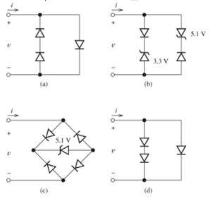
Figure P9.7
Expert Solution & Answer
Want to see the full answer?
Check out a sample textbook solution
Students have asked these similar questions
No chatgpt pls will upvote
circuit find value of VAB using Super Position Theorem
dc circuit vth rth rl thevenin and then maximum transer and value of rl
Chapter 9 Solutions
Electrical Engineering: Principles & Applications (7th Edition)
Knowledge Booster


Learn more about
Need a deep-dive on the concept behind this application? Look no further. Learn more about this topic, electrical-engineering and related others by exploring similar questions and additional content below.Similar questions
- Please solve in detailarrow_forward6.7 The transmitting aerial shown in Fig. Q.3 is supplied with current at 80 A peak and at frequency 666.66 kHz. Calculate (a) the effective height of the aerial, and (b) the electric field strength produced at ground level 40 km away. 60 m Fig. Q.3 Input 48 m Eartharrow_forwardox SIM 12.11 Consider the class B output stage, using MOSFETs, shown in Fig. P12.11. Let the devices have |V|= 0.5 V and μC WIL = 2 mA/V². With a 10-kHz sine-wave input of 5-V peak and a high value of load resistance, what peak output would you expect? What fraction of the sine-wave period does the crossover interval represent? For what value of load resistor is the peak output voltage reduced to half the input? Figure P12.11 +5 V Q1 Q2 -5Varrow_forward
- 4 H ་་་་་་་ 四一周 A H₂ Find out put c I writ R as a function G, H, Harrow_forward4 H A H₂ 四一周 Find out put c I writ R as a function G, H, Harrow_forward8. (a) In a Round-Robin tournament, the Tigers beat the Blue Jays, the Tigers beat the Cardinals, the Tigers beat the Orioles, the Blue Jays beat the Cardinals, the Blue Jays beat the Orioles and the Cardinals beat the Orioles. Model this outcome with a directed graph. https://www.akubihar.com (b) (c) ✓ - Let G = (V, E) be a simple graph. Let R be the relation on V consisting of pairs of vertices (u, v) such that there is a path from u to vor such that u= v. Show that R is an equivalence relation. 3 3 Determine whether the following given pair of directed graphs, shown in Fig. 1 and Fig. 2, are isomorphic or not. Exhibit an isomorphism or provide a rigorous argument that none exists. 4+4=8 Աշ աշ ИНИЯ Fig. 1 Fig. 2 Querarrow_forward
- EXAMPLE 4.5 Objective: Determine ID, circuit. V SG' SD Vs and the small - signal voltage gain of a PMOS transistor Consider the circuit shown in Figure 4.20(a). The transistor parameters are A K = 0.80m- V Р _2’TP = 0.5V, and λ = 0 Varrow_forwardNeed a solution and don't use chatgptarrow_forwardNeed a solarrow_forward
arrow_back_ios
SEE MORE QUESTIONS
arrow_forward_ios
Recommended textbooks for you
 Introductory Circuit Analysis (13th Edition)Electrical EngineeringISBN:9780133923605Author:Robert L. BoylestadPublisher:PEARSON
 Delmar's Standard Textbook Of ElectricityElectrical EngineeringISBN:9781337900348Author:Stephen L. HermanPublisher:Cengage Learning
 Programmable Logic ControllersElectrical EngineeringISBN:9780073373843Author:Frank D. PetruzellaPublisher:McGraw-Hill Education
 Fundamentals of Electric CircuitsElectrical EngineeringISBN:9780078028229Author:Charles K Alexander, Matthew SadikuPublisher:McGraw-Hill Education
 Electric Circuits. (11th Edition)Electrical EngineeringISBN:9780134746968Author:James W. Nilsson, Susan RiedelPublisher:PEARSON
 Engineering ElectromagneticsElectrical EngineeringISBN:9780078028151Author:Hayt, William H. (william Hart), Jr, BUCK, John A.Publisher:Mcgraw-hill Education,
Introductory Circuit Analysis (13th Edition)
Electrical Engineering
ISBN:9780133923605
Author:Robert L. Boylestad
Publisher:PEARSON
Delmar's Standard Textbook Of Electricity
Electrical Engineering
ISBN:9781337900348
Author:Stephen L. Herman
Publisher:Cengage Learning
Programmable Logic Controllers
Electrical Engineering
ISBN:9780073373843
Author:Frank D. Petruzella
Publisher:McGraw-Hill Education
Fundamentals of Electric Circuits
Electrical Engineering
ISBN:9780078028229
Author:Charles K Alexander, Matthew Sadiku
Publisher:McGraw-Hill Education
Electric Circuits. (11th Edition)
Electrical Engineering
ISBN:9780134746968
Author:James W. Nilsson, Susan Riedel
Publisher:PEARSON
Engineering Electromagnetics
Electrical Engineering
ISBN:9780078028151
Author:Hayt, William H. (william Hart), Jr, BUCK, John A.
Publisher:Mcgraw-hill Education,
02 - Sinusoidal AC Voltage Sources in Circuits, Part 1; Author: Math and Science;https://www.youtube.com/watch?v=8zMiIHVMfaw;License: Standard Youtube License