Introductory Circuit Analysis (13th Edition)
13th Edition
ISBN: 9780133923605
Author: Robert L. Boylestad
Publisher: PEARSON
expand_more
expand_more
format_list_bulleted
Question

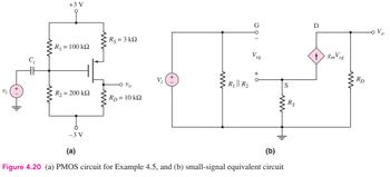
Transcribed Image Text:+3V
Ry = 3 k2
R1 = 100 k2
V:
R₁ || R₂
Vi
R2 = 200k2
Ry = 10 k2
Vsg
+
S
-3 V
(a)
(b)
Figure 4.20 (a) PMOS circuit for Example 4.5, and (b) small-signal equivalent circuit
Rs
D
8mVsg
ww
RD

Transcribed Image Text:EXAMPLE 4.5
Objective: Determine ID,
circuit.
V
SG'
SD
Vs and the small - signal voltage gain of a PMOS transistor
Consider the circuit shown in Figure 4.20(a). The transistor parameters are
A
K = 0.80m- V
Р
_2’TP
= 0.5V, and λ = 0
V
Expert Solution
This question has been solved!
Explore an expertly crafted, step-by-step solution for a thorough understanding of key concepts.
Step by stepSolved in 2 steps with 6 images

Knowledge Booster
Similar questions
- Explain all the stepsarrow_forwardWhy is there a difference in the beta value? (D. C) and the beta (A. C) value in some transistor output characteristic schemes.arrow_forwardIdeally, a dc load line is a straight line drawn on the collector characteristic curves between VCE(cutoff) and /C(sat) the Q-point and cutoff the Q-point and saturation IB = 0 and IB = IC / Bdcarrow_forward
- Explain the stepsarrow_forwardObjective: Determine the small-signal voltage gain of a circuit biased with a constant- current source and incorporating a source bypass capacitor. +5 V Rp = 7 kn For the circuit shown in Figure 4.21, the transistor parameters are: VTN = 0.8 V, K, = 1 mA/V?, and = 0. o vo RG= 200 k2 +Cs lo = 0.5 mA 4 -5 Varrow_forwardn EXERCISE PROBLEM Ex 4.5: For the circuit shown in Figure 4.19, the transistor parameters are VTN = 0.8 V, K₂ = 1 mA/V², and λ = 0. (a) From the dc analysis, find ID and VDSQ. (b) Determine the small-signal voltage gain. (Ans. (a) ID = 0.494 mA, VDSQ = 6.30 V; (b) A₁ = -5.78).arrow_forward
- EXERCISE PROBLEM Ex 4.6: The common-source amplifier in Figure 4.23 has transistor parameters = 40 μA/V², W/L = 40, VTP = −0.4 V, and λ = 0.02 V-1. (a) Determine IDQ and VSDQ. (b) Find the small-signal voltage gain. (Ans. (a) IDQ = 1.16 mA, VSDQ = 2.29 V; (b) A₁ = -3.68) CCI Vi www +3 V Rs = 1.2 k RG = 100 k - Vo RD = 2 k -3 V Figure 4.23 Figure for Exercise Ex 4.6 Csarrow_forwardEXERCISE PROBLEM Ex 4.2: For the circuit shown in Figure 4.1, VDD = 3.3 V and RD = 10 ks. The transistor parameters are VTN = 0.4 V, k = 100 μA/V², W/L = 50, and λ= 0.025 V1. Assume the transistor is biased such that IDQ = 0.25 mA. (a) Verify that the transistor is biased in the saturation region. (b) Determine the small- signal parameters gm and ro. (c) Determine the small-signal voltage gain. (Ans. (a) VGsQ = 0.716 V and VDSQ = 0.8 V so that VDS > VDs (sat); (b) gm 1.58 mA/V, ro = 160 ks2; (c) -14.9)arrow_forwardSmall Signal Analysis Vcc Ves Problem #4 - Vcc 4а) For the circuit shown to the right, draw the Ry Vour small signal equivalent circuit (including r.). Be sure to label everything (e.g., Vbe, gm, etc.) Do not assume identical transistors (i.e., keep all subscripts). Use Qz correct small signal notation! 4b) For the small signal equivalent circuit shown on the right, solve for Rin. Do not assume identical transistors. Vbei 9m2 Vbe2 R 02 Vbez Darrow_forward
- d. For the common-base configuration, an ac signal of 10 mV is applied, resulting in an ac emitter current of 0.5 mA. If alpha is 0.980 and RL = 1.2 k2, determine Zj. Vo, and Ay.arrow_forwardQUESTION 4 a) Discuss four advantages of field effect transistor (FET) over bipolar junction transistor (BJT). b) With the aid of suitable diagrams, explain the primary difference between n-channel depletion and enhancement type metal oxide semiconductor field effect transistors (MOSFETS).arrow_forward5- a-) Define the MOSFET in the figure, explain by drawing its input and output circuit characteristics.b-) Since k=0.1 mA/V2, VGS=5V and VT=2.5V for this MOSFET, find the VDS voltage using the circuit.arrow_forward
arrow_back_ios
SEE MORE QUESTIONS
arrow_forward_ios
Recommended textbooks for you
 Introductory Circuit Analysis (13th Edition)Electrical EngineeringISBN:9780133923605Author:Robert L. BoylestadPublisher:PEARSON
 Delmar's Standard Textbook Of ElectricityElectrical EngineeringISBN:9781337900348Author:Stephen L. HermanPublisher:Cengage Learning
 Programmable Logic ControllersElectrical EngineeringISBN:9780073373843Author:Frank D. PetruzellaPublisher:McGraw-Hill Education
 Fundamentals of Electric CircuitsElectrical EngineeringISBN:9780078028229Author:Charles K Alexander, Matthew SadikuPublisher:McGraw-Hill Education
 Electric Circuits. (11th Edition)Electrical EngineeringISBN:9780134746968Author:James W. Nilsson, Susan RiedelPublisher:PEARSON
 Engineering ElectromagneticsElectrical EngineeringISBN:9780078028151Author:Hayt, William H. (william Hart), Jr, BUCK, John A.Publisher:Mcgraw-hill Education,

Introductory Circuit Analysis (13th Edition)
Electrical Engineering
ISBN:9780133923605
Author:Robert L. Boylestad
Publisher:PEARSON

Delmar's Standard Textbook Of Electricity
Electrical Engineering
ISBN:9781337900348
Author:Stephen L. Herman
Publisher:Cengage Learning

Programmable Logic Controllers
Electrical Engineering
ISBN:9780073373843
Author:Frank D. Petruzella
Publisher:McGraw-Hill Education

Fundamentals of Electric Circuits
Electrical Engineering
ISBN:9780078028229
Author:Charles K Alexander, Matthew Sadiku
Publisher:McGraw-Hill Education

Electric Circuits. (11th Edition)
Electrical Engineering
ISBN:9780134746968
Author:James W. Nilsson, Susan Riedel
Publisher:PEARSON

Engineering Electromagnetics
Electrical Engineering
ISBN:9780078028151
Author:Hayt, William H. (william Hart), Jr, BUCK, John A.
Publisher:Mcgraw-hill Education,