
Find the maximum negative bending moment at point B.
Answer to Problem 1P
The maximum negative bending moment at point B is
Explanation of Solution
Given Information:
The concentrated live load (P) is 75 kN.
Calculation:
Apply a 1 kN unit moving load at a distance of x from left end A.
Sketch the free body diagram of beam as shown in Figure 1.
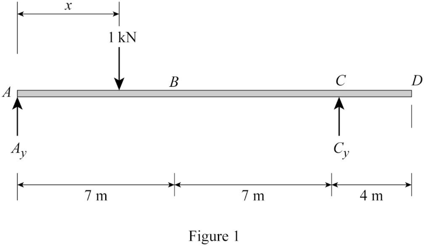
Refer Figure 1.
Find the equation of support reaction
Take moment about point A.
Consider moment equilibrium at point A.
Consider clockwise moment as positive and anticlockwise moment as negative.
Sum of moment at point A is zero.
Find the equation of support reaction
Apply vertical equilibrium equation of forces.
Consider upward force as positive
Substitute
Find the equation of moment at B.
Apply 1 kN at just left of B
Sketch the free body diagram of the section AB as shown in Figure 2.
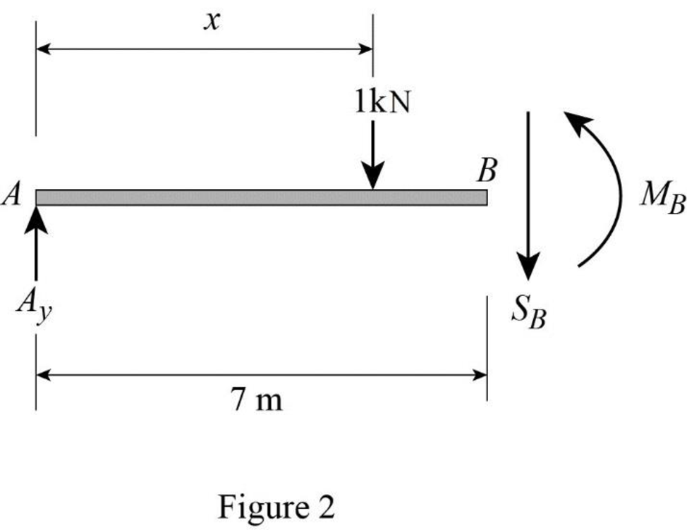
Refer Figure 2.
Consider moment at B.
Consider clockwise moment as positive and anticlockwise moment as negative.
Substitute
Apply 1 kN at just right of B
Sketch the free body diagram of the section BD as shown in Figure 3.
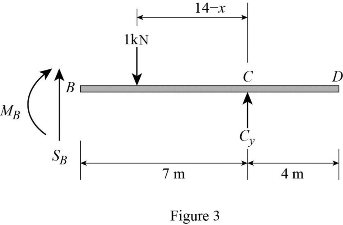
Refer Figure 3.
Consider moment at B.
Consider clockwise moment as positive and anticlockwise moment as negative.
Find the equation of moment at B of portion BC
Substitute
Thus, the equations of the influence line for
Find the value of influence line ordinate of moment at various points of x using the Equations (3) and (4) and summarize the value as in Table 1.
| x | |
| 0 | 0 |
| 7 | |
| 14 | 0 |
| 28 | –2 |
Draw the influence lines for the moment at point B using Table 4 as shown in Figure 4.
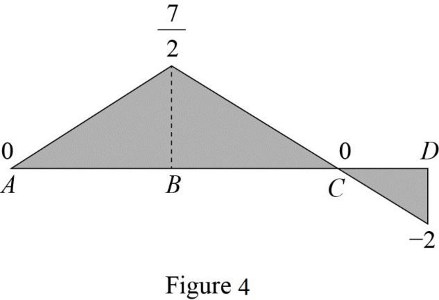
Refer Figure 4,
The maximum negative influence line ordinate of bending moment at B is
Find the maximum negative bending moment at point B using the equation.
Substitute 75 kN for P and
Therefore, the maximum negative bending moment at point B is
Want to see more full solutions like this?
Chapter 9 Solutions
Structural Analysis, Si Edition (mindtap Course List)

- 5.11: Determine the absolute maximum sh earing force and bending moment in a simply supported beam of 50 m span due to the series of four moving concentrated loads shown in Fig. P5.11. 20 kN 20 kN 30 kN 30 kN ↑ t my 6 m 6 m 50 m Figure P5.11arrow_forwardDetermine the absolute maximum shear in a 15-m-long simply supported beam due to the series of three moving concentrated loads shown in Fig. P9.13.arrow_forward4.74 For the frame shown, determine the magnitude of the pin reaction at B. Neglect the weight of the frame. 2m B 1.8 m 3m C 15 kN/m 12 kN/m Fig. P4.74arrow_forward
- 7.37 and 7.38 For the beam and loading shown, (a) draw the shear and bending-moment diagrams, (b) determine the maximum absolute values of the shear and bending moment. Fig. P7.37 6 kips 12 kips с 2 ft D 2 ft 2 ft E 4.5 kips 2 ft Barrow_forwardQ-1 The rigid frame shown in Fig.I is pinned at A and roller supported at D. For the given loading, determine the support reactions and draw the axial force, shear force and bending moment diagrams. 17.5 kN/m 4.5 m 112 kN в + 67.5 kN 6 m 4.5 m Fig.1 9 marrow_forwardQ.2. A beam ABC with an overhang at one end supports a uniform load of intensity 12 kN/m and a concentrated load of magnitude 2.4 kN as shown in figure (2). Draw the shear-force and bending-moment diagrams for this beam. 12 kN/m -1.6 m- H B -1.6 m- Fig. (2) 2.4 kN 1.6m icarrow_forward
- 60 100 60 30 200 10 50 100s 2000 400 300 120 VA 12" FIG. P 2-17 6' 2-18. Determine the resultant of the parallel, coplanar force system shown in Fig. P 2-18 and locate it with respect to point A. FIG. P 2-18arrow_forward706. For the propped beam shown in Fig. P-706, determine the reaction R and sketch the shear and moment diagrams. wo conjugate beam method Figure P-706 Rarrow_forward1. Shown in Figure 1 is a beam subjected to varying loadings and a point load. 12 kN 3kN/m 6 kN/m a) Determine the magnitude and direction of the force equivalent to the forcing system. Specify its location on the beam from point B. A 5m b) Calculate for the support reactions at A and B. Fig. Iarrow_forward
- 705. Compute the reaction R and sketch the shear and moment diagrams for the propped beam shown in Fig. P-705. Ans. R woL/10 %3D conjugate beam method Wo L Figure P-705 Rarrow_forwardThe continuous beam ABC, Fig.2, is fixed at A and pinned at C with a roller support at B. The point loads of 30 KN and 20 kN act at the midpoints of AB and BC respectively. Use the method of consistent deformations to determine the reaction components and draw the shear force and bending moment diagrams for the beam. (constant EI). AH F 30 kN ↓ 12m 20 kN 12m Fig.2arrow_forward(6.70 A beam with two equal overhangs carries a unitoad between supports A and B and concentrated loads at the free ends. shown in Fig. P6.70. (a) Write an expression for distributed load, shear, and moment acting in the beam. (b) Draw shear and moment diagrams. y P=-10 KN A -1 m w = 15 kN/m 2 m Figure P6.70 P=10 KN B 123 Narrow_forward

 Structural Analysis (10th Edition)Civil EngineeringISBN:9780134610672Author:Russell C. HibbelerPublisher:PEARSON
 Principles of Foundation Engineering (MindTap Cou...Civil EngineeringISBN:9781337705028Author:Braja M. Das, Nagaratnam SivakuganPublisher:Cengage Learning
 Fundamentals of Structural AnalysisCivil EngineeringISBN:9780073398006Author:Kenneth M. Leet Emeritus, Chia-Ming Uang, Joel LanningPublisher:McGraw-Hill Education
 Traffic and Highway EngineeringCivil EngineeringISBN:9781305156241Author:Garber, Nicholas J.Publisher:Cengage Learning