
Loose Leaf for Engineering Circuit Analysis Format: Loose-leaf
9th Edition
ISBN: 9781259989452
Author: Hayt
Publisher: Mcgraw Hill Publishers
expand_more
expand_more
format_list_bulleted
Concept explainers
Videos
Textbook Question
Chapter 8.6, Problem 10P
For the circuit of Fig. 8.37, find vc(t) at t equal to (a) 0−; (b) 0+; (c) ∞; (d) 0.08 s.
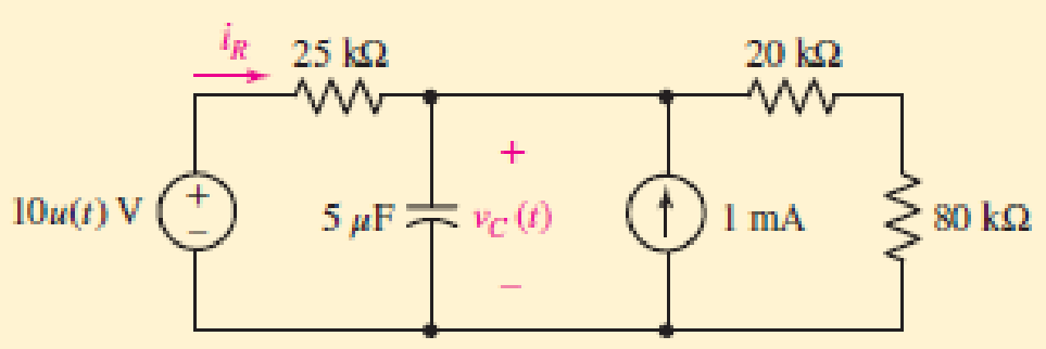
■ FIGURE 8.37
Expert Solution & Answer
Want to see the full answer?
Check out a sample textbook solution
Students have asked these similar questions
Don't use ai to answer I will report you answer
Not use ai please
49.
For the circuit below, what is the best connection of the capacitor to filte
voltage?
ბი
DO
A O
BO
wwwww
wwwww
M
m
H
E
LOAD
Chapter 8 Solutions
Loose Leaf for Engineering Circuit Analysis Format: Loose-leaf
Ch. 8.1 - For the circuit in Fig. 8.2, what value of...Ch. 8.1 - Noting carefully how the circuit changes once the...Ch. 8.2 - In a source-free series RC circuit, find the...Ch. 8.3 - Prob. 4PCh. 8.3 - Prob. 5PCh. 8.4 - Prob. 6PCh. 8.4 - Prob. 7PCh. 8.4 - Prob. 8PCh. 8.5 - Evaluate each of the following at t = 0.8: (a)...Ch. 8.6 - For the circuit of Fig. 8.37, find vc(t) at t...
Ch. 8.7 - Prob. 11PCh. 8.7 - The voltage source 60 40u(t) V is in series with...Ch. 8.7 - Prob. 13PCh. 8.8 - Prob. 14PCh. 8.8 - Prob. 15PCh. 8 - A source-free RC circuit has R = 4 k and C = 22 F,...Ch. 8 - A source-free RC circuit has v(0) = 12 V and R =...Ch. 8 - The resistor in the circuit of Fig. 8.51 has been...Ch. 8 - Prob. 4ECh. 8 - Prob. 5ECh. 8 - Prob. 6ECh. 8 - Prob. 7ECh. 8 - Prob. 8ECh. 8 - Prob. 9ECh. 8 - The switch in Fig. 8.56 has been closed for a long...Ch. 8 - For the circuit in Fig. 8.56, find (a) the total...Ch. 8 - Design a capacitor-based circuit that can achieve...Ch. 8 - (a) Graph the function f (t) = 10e2t over the...Ch. 8 - The current i(t) flowing through a 1 k resistor is...Ch. 8 - Radiocarbon dating has a similar exponential time...Ch. 8 - For the circuit of Fig. 8.4, compute the time...Ch. 8 - Design a circuit which will produce a current of 1...Ch. 8 - Prob. 18ECh. 8 - Prob. 19ECh. 8 - Referring to the circuit shown in Fig. 8.11,...Ch. 8 - Prob. 21ECh. 8 - With the assumption that the switch in the circuit...Ch. 8 - The switch in Fig. 8.57 has been closed since...Ch. 8 - The switch in the circuit of Fig. 8.58 has been...Ch. 8 - Assuming the switch initially has been open for a...Ch. 8 - (a) Obtain an expression for v(t), the voltage...Ch. 8 - For the circuit of Fig. 8.61, determine ix, iL,...Ch. 8 - Prob. 28ECh. 8 - Prob. 29ECh. 8 - Prob. 30ECh. 8 - Prob. 31ECh. 8 - (a) Obtain an expression for vx as labeled in the...Ch. 8 - Prob. 33ECh. 8 - Prob. 34ECh. 8 - Prob. 35ECh. 8 - Prob. 36ECh. 8 - Prob. 37ECh. 8 - The switch in Fig. 8.70 is moved from A to B at t...Ch. 8 - Prob. 39ECh. 8 - Prob. 40ECh. 8 - Evaluate the following functions at t = 1, 0, and...Ch. 8 - Prob. 42ECh. 8 - Prob. 43ECh. 8 - Prob. 44ECh. 8 - You can use MATLAB to represent the unit-step...Ch. 8 - With reference to the circuit depicted in Fig....Ch. 8 - For the circuit given in Fig. 8.75, (a) determine...Ch. 8 - Prob. 48ECh. 8 - Prob. 49ECh. 8 - You build a portable solar charging circuit...Ch. 8 - The switch in the circuit of Fig. 8.78 has been...Ch. 8 - The switch in the circuit of Fig. 8.78 has been...Ch. 8 - Prob. 53ECh. 8 - Prob. 54ECh. 8 - Prob. 55ECh. 8 - For the circuit represented in Fig. 8.82, (a)...Ch. 8 - Prob. 58ECh. 8 - Prob. 59ECh. 8 - For the circuit given in Fig. 8.85, (a) determine...Ch. 8 - The circuit depicted in Fig. 8.86 contains two...Ch. 8 - Prob. 62ECh. 8 - Prob. 63ECh. 8 - A series RL circuit has a voltage that steps from...Ch. 8 - For the two-source circuit of Fig. 8.89, note that...Ch. 8 - (a) Obtain an expression for iL as labeled in Fig....Ch. 8 - Obtain an expression for i(t) as labeled in the...Ch. 8 - Obtain an expression for i1 as indicated in Fig....Ch. 8 - Plot the current i(t) in Fig. 8.93 if (a) R = 10 ;...Ch. 8 - A dc motor can be modeled as a series RL circuit...Ch. 8 - Prob. 71ECh. 8 - Prob. 72ECh. 8 - A series RC sequentially switched circuit has R =...Ch. 8 - Refer to the circuit of Fig. 8.95, which contains...Ch. 8 - In the circuit of Fig. 8.95, a 3 mF capacitor is...Ch. 8 - Prob. 78E
Knowledge Booster


Learn more about
Need a deep-dive on the concept behind this application? Look no further. Learn more about this topic, electrical-engineering and related others by exploring similar questions and additional content below.Similar questions
- 5.25. Determine the corner frequency resulting from Cin in Fig. 5.47(d). For simplicity, assume C₁ is a short circuit. TVDD C₁ M2 RF Vin H w - Vout Cin M₁arrow_forwardIn the below circuit, find out the value of equivalent Thevenin's voltage and Thevenin's resistance at the terminal. 2000 0.25 A 400 2 800 2 0.1 Aarrow_forwardQ1: For the circuit shown in Figure-1, (a) Calculate the equivalent resistance of the circuit, RAB at the terminals A and B. [10] (b) When 50V dc source is switched at terminals A-B, solve for the voltage V₁ at the location shown. [10] 50V www 12Ω 10Ω 5Ω www www A + B 200 Figure-1 www 10Ω ww 25Ω 100arrow_forward
- a. Write a PLC ladder diagram that allows the teacher to teach AND, OR, and XOR logic gates through using three PLC's digital input points and only one digital output point.arrow_forwardrately by PRACTICE 4.2 For the circuit of Fig. 4.5, compute the voltage across each curren source. 202 ww 3A 30 ww 4Ω S 50 www Reference node FIGURE 4.5 Ans: V3A =5.235 V; 7A = 11.47 V. 7 Aarrow_forwardQ2) a) design and show me your steps to convert the following signal from continuous form to digital form: s(t)=3sin(3πt) -1 373 Colesarrow_forward
- A sequence is defined by the relationship r[n] = [h[m]h[n+m]=hn*h-n where h[n] is a minimum-phase sequence and r[n]= 4 4 (u[n]+ 12" [n-1] 3 (a) Find R(z) and sketch the pole-zero diagram. (b) Determine the minimum-phase sequence h[n] to within a scale factor of ±1. Also, determine the z-transform H(z) of h[n].arrow_forwardusıng j-k and D flipflop design a counter that counts 0,2,1 again as shown below ın the tablearrow_forwardfind the minterms of the followıng boolean expressıon desıgn F's cırcuit using one of the approciate decoders given below and a NOR gateF(A,B,C,D)=(A+'BC)(B 'C+'A 'D + CD)arrow_forward
- 64) answer just two from three the following terms: A) Design ADC using the successive method if the Vmax=(3) volt, Vmin=(-2) volt, demonstrate the designing system for vin-1.2 volt. Successive Approximation ADC Input Voltage-1.1 V -4-3.5-3 -2.5 -2 -1.5 +1 -0.5 0 0.5 1 1.5 2 2.5 3 3.5 1 T -8 -7 -6 -5 -3 +2 -1 0 1 2 3 4 5 6 7 X=1??? 1st guess: -0.25 V (too high) X=11?? 2nd guess: -2.25 V (too low) 3rd guess: -1.25 V (too low) X=1110 X=111? 4th guess: -0.75 V (too high) Make successive guesses and use a comparator to tell whether your guess is too high or too low. Each guess determines one bit of the answer and cuts the number of remaining possibilities in half.arrow_forwardDatacommunıcatıonin a commuinaction ASYNCHRONOUS TRANSMİTİON is used in this transmistion 7-bit chatacter will be transfered even parity will be used ,stop element is as 1,5 bits a)=select a chracter yourself and dısplay the signal transfered in this transmission , and calculate the overhead in this transmisionarrow_forward(i) Find the inverse z-transform of the system H(z) = for the following regions of convergence. Write in the final answer for each case in the allocated rectangular box below (a) |z| 3 (c) 1arrow_forwardarrow_back_iosSEE MORE QUESTIONSarrow_forward_ios
Recommended textbooks for you
 Introductory Circuit Analysis (13th Edition)Electrical EngineeringISBN:9780133923605Author:Robert L. BoylestadPublisher:PEARSON
 Delmar's Standard Textbook Of ElectricityElectrical EngineeringISBN:9781337900348Author:Stephen L. HermanPublisher:Cengage Learning
 Programmable Logic ControllersElectrical EngineeringISBN:9780073373843Author:Frank D. PetruzellaPublisher:McGraw-Hill Education
 Fundamentals of Electric CircuitsElectrical EngineeringISBN:9780078028229Author:Charles K Alexander, Matthew SadikuPublisher:McGraw-Hill Education
 Electric Circuits. (11th Edition)Electrical EngineeringISBN:9780134746968Author:James W. Nilsson, Susan RiedelPublisher:PEARSON
 Engineering ElectromagneticsElectrical EngineeringISBN:9780078028151Author:Hayt, William H. (william Hart), Jr, BUCK, John A.Publisher:Mcgraw-hill Education,
Introductory Circuit Analysis (13th Edition)
Electrical Engineering
ISBN:9780133923605
Author:Robert L. Boylestad
Publisher:PEARSON
Delmar's Standard Textbook Of Electricity
Electrical Engineering
ISBN:9781337900348
Author:Stephen L. Herman
Publisher:Cengage Learning
Programmable Logic Controllers
Electrical Engineering
ISBN:9780073373843
Author:Frank D. Petruzella
Publisher:McGraw-Hill Education
Fundamentals of Electric Circuits
Electrical Engineering
ISBN:9780078028229
Author:Charles K Alexander, Matthew Sadiku
Publisher:McGraw-Hill Education
Electric Circuits. (11th Edition)
Electrical Engineering
ISBN:9780134746968
Author:James W. Nilsson, Susan Riedel
Publisher:PEARSON
Engineering Electromagnetics
Electrical Engineering
ISBN:9780078028151
Author:Hayt, William H. (william Hart), Jr, BUCK, John A.
Publisher:Mcgraw-hill Education,
ENA 9.2(1)(En)(Alex) Sinusoids & Phasors - Explanation with Example 9.1 ,9.2 & PP 9.2; Author: Electrical Engineering Academy;https://www.youtube.com/watch?v=vX_LLNl-ZpU;License: Standard YouTube License, CC-BY
Electrical Engineering: Ch 10 Alternating Voltages & Phasors (8 of 82) What is a Phasor?; Author: Michel van Biezen;https://www.youtube.com/watch?v=2I1tF3ixNg0;License: Standard Youtube License