
Concept explainers
Videos
Refer to the circuit of Fig. 8.95, which contains a voltage-controlled dependent voltage source in addition to two resistors. (a) Compute the circuit time constant. (b) Obtain an expression for vx valid for all t. (c) Plot the power dissipated in the 4 Ω resistor over the range of six time constants. (d) Repeat parts (a) to (c) if the dependent source is installed in the circuit upside down. (e) Are both circuit configurations “stable”? Explain.
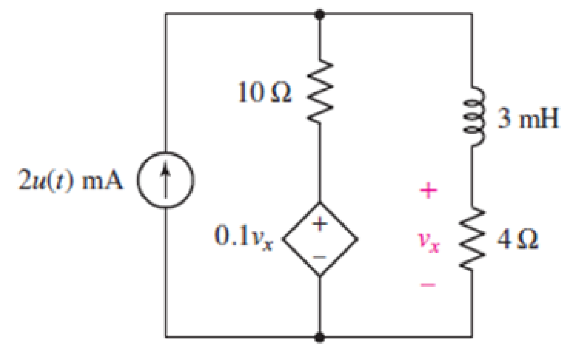
Figures 8.95
(a)
Find the circuit time constant.
Answer to Problem 76E
The time constant of the circuit is
Explanation of Solution
Formula used:
The expression for the resistance of the circuit is as follows:
Here,
The expression for the time constant of circuit is as follows:
Here,
Calculation:
To find equivalent resistance of a circuit the independent current source is replaced by open circuit and
The circuit diagram is redrawn as shown in Figure 1.
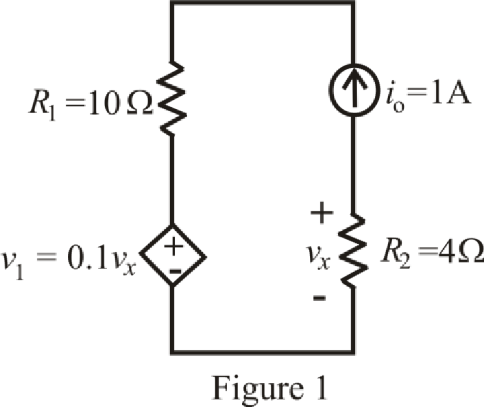
Refer to the redrawn Figure 1:
Apply KVL in mesh 1:
Here,
Substitute
The expression for voltage across the
Here,
Substitute
Substitute
Rearrange for
Substitute
So, the equivalent resistance across inductor is
Substitute
So the time constant of the circuit is
Conclusion:
Thus, the time constant of the circuit is
(b)
Obtain an expression for
Answer to Problem 76E
The expression for the voltage
Explanation of Solution
Formula used:
The expression for the final response of the circuit valid for all
Here,
Calculation:
The unit-step forcing function as a function of time which is zero for all values of its argument less than zero and which is unity for all positive values of its argument.
Here,
The independent current source is:
Substitute
The current through
The
So, the value of the current flowing through the inductor for
The inductor does not allow sudden change in the current.
So,
Therefore, the current flowing in the circuit for
Substitute
So, the current flowing through the
The circuit diagram is redrawn as shown in Figure 2 for
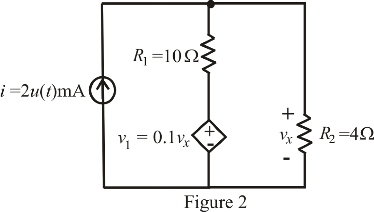
Refer to the redrawn Figure 2:
Apply KCL in the circuit:
Substitute
Rearrange for
The expression for the current flowing through
Here,
Substitute
So, the current flowing through
Substitute
The expression for the voltage across the
Substitute
Conclusion:
Thus, the expression for the voltage
(c)
Plot the power dissipated in the
Explanation of Solution
Given data:
The range of the time is six time constant.
Formula used:
The expression for the power dissipated in the
Here,
Calculation:
Substitute
The time constant of the circuit is
The different value for the power dissipated in the
The graph for power dissipated in the
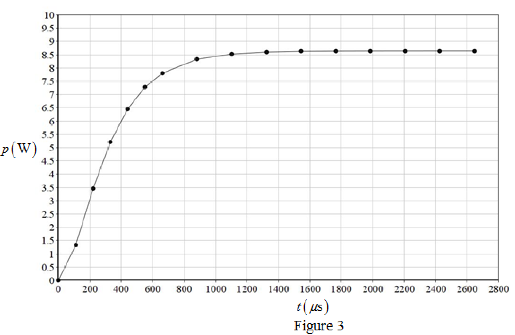
Calculation:
Thus, the graph for power dissipated in the
Conclusion:
(d)
Repeat parts (a) to (c) if the dependent source is installed in the circuit upside down.
Explanation of Solution
Calculation:
To find equivalent resistance of a circuit the independent current source is replaced by open circuit and
The circuit diagram is redrawn as shown in Figure 4:
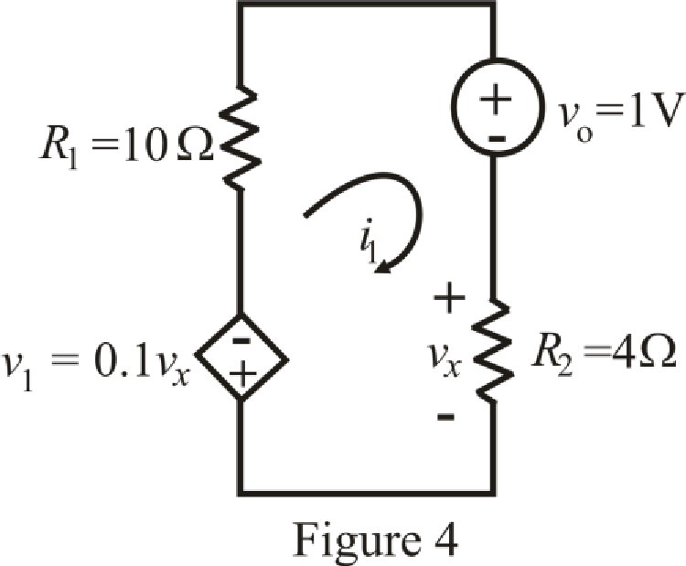
Refer to the redrawn Figure 4:
Apply KVL in mesh 1:
Here,
Substitute
The expression for voltage across the
Here,
Substitute
Substitute
Rearrange for
Substitute
So, the equivalent resistance across inductor is
Substitute
So, the time constant of the circuit is
The unit-step forcing function as a function of time which is zero for all values of its argument less than zero and which is unity for all positive values of its argument.
Here,
The independent voltage source is:
Substitute
The current through
The
So, the value of the current flowing through the inductor for
The inductor does not allow sudden change in the current.
So,
Therefore, the current flowing in the circuit for
Substitute
So, the current flowing through the
The circuit diagram is redrawn as shown in Figure 5 for
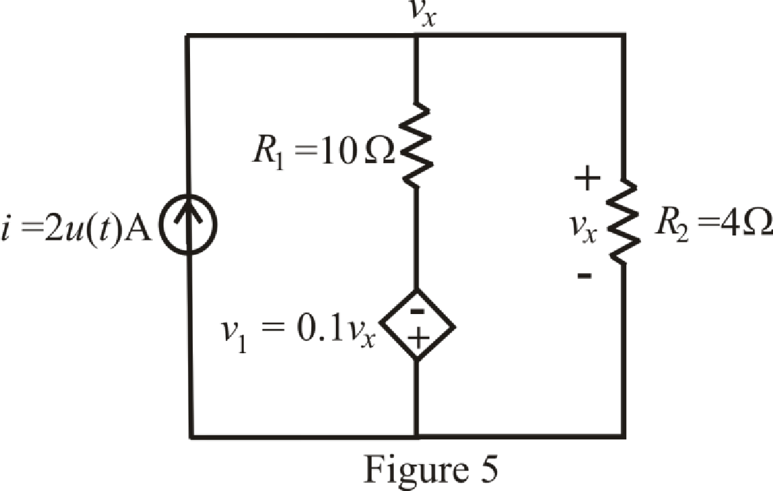
Refer to the redrawn Figure 5:
Apply KCL in the circuit:
Substitute
Rearrange for
The expression for the current flowing through
Here,
Substitute
So, the current flowing through
Substitute
The expression for the voltage across the
Substitute
So, the expression for the voltage
Substitute
The time constant of the circuit is
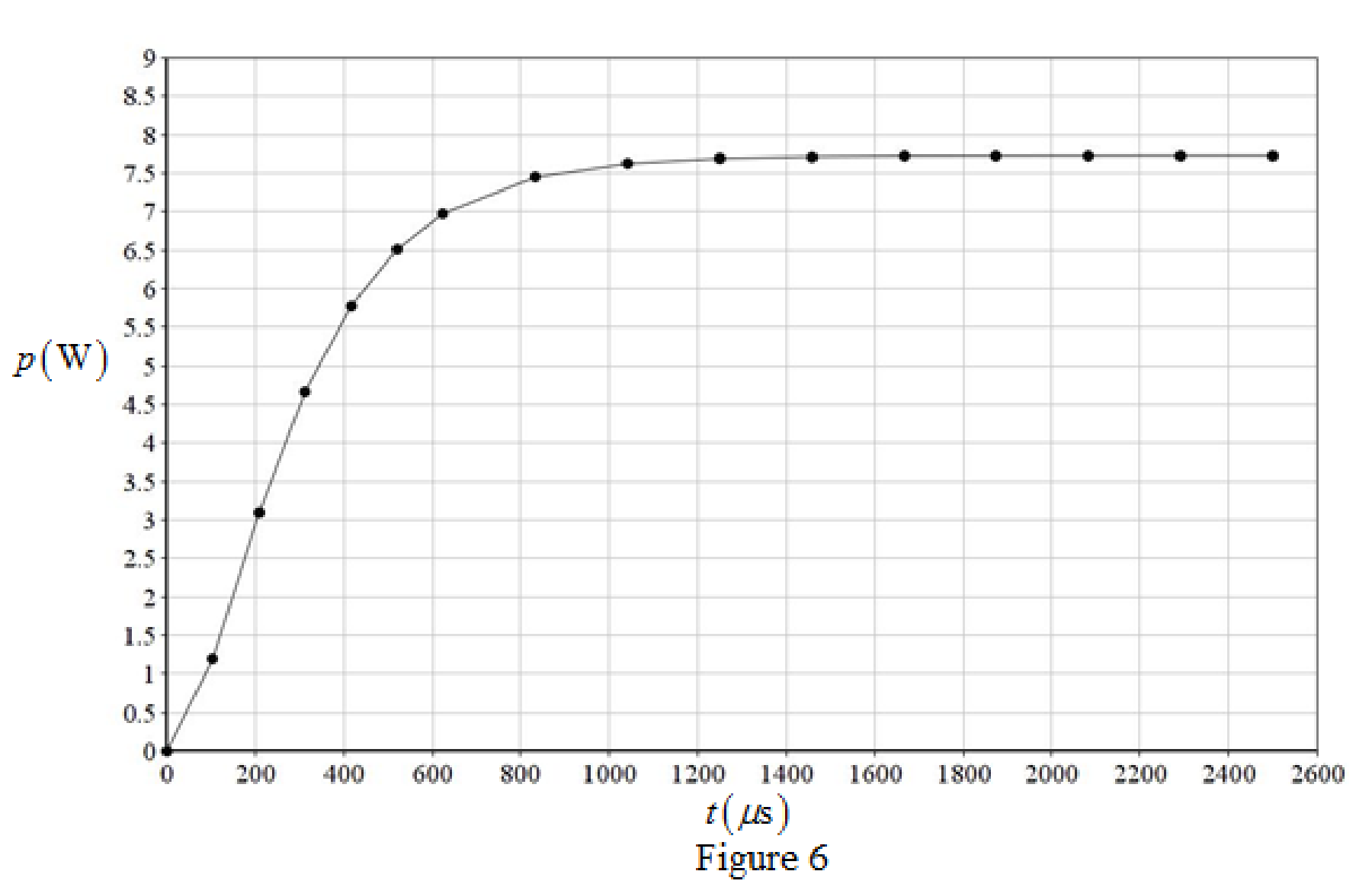
The different value for the power dissipated in the
The graph for power dissipated in the
Conclusion:
Thus, the time constant of the circuit is
(e)
Are both circuit configurations “stable”? Explain.
Answer to Problem 76E
Both circuit configurations are “stable”.
Explanation of Solution
Refer to Figure 3 and Figure 6:
The response (output power dissipated in the
So, both circuit configurations “stable”.
Conclusion:
Thus, both circuit configurations are “stable”.
Want to see more full solutions like this?
Chapter 8 Solutions
Loose Leaf for Engineering Circuit Analysis Format: Loose-leaf
Additional Engineering Textbook Solutions
Basic Engineering Circuit Analysis
Electronics Fundamentals: Circuits, Devices & Applications
Electric Circuits (10th Edition)
Electric Circuits. (11th Edition)
Fundamentals of Applied Electromagnetics (7th Edition)
Principles and Applications of Electrical Engineering


- The switch in Fig. 8.73 is moved from A to B at t = 0 after being at A for a long time. This places the two capacitors in series, thus allowing equal and opposite de voltages to be trapped on the capacitors (d) Find vr(t), t > 0. (e) Find i(t). (f) Find vi(t) and v2(t) from i(t) and the initial values. (g) Show that the stored energy at i = 0 plus the total energy dissipated in the 20 kS2 resistor is equal to the energy stored in the capacitors at t = 0arrow_forwardidentify the following 1. If the pole’s real value is positive and is located on the right side of the S-plane. The system exponentially ____________.2. Is a continuous connection of branches from one node to another with all arrowheads in the same direction.3. Knowing the location of the pole in the S-plane determines the ______________ of the system.arrow_forwarddifferential equations applications. A 12-volt battery is connected to a series circuit in which the inductor is 1/2 henry and the resistance is 10 ohms. Determine current i, if the initial current is zero.arrow_forward
- If the roots of the characteristic equation are -3,0 then the system is _________________________. Marginally stable Conditionally stable Stable Unstablearrow_forwardObtain an expression for i1 as indicated in Fig. 8.85 that is valid for all values of t.arrow_forwardevaluate the circuitarrow_forward
- For the circuit shown in Fig 8, find i, vc, and iL, as well as the energy accumulated in the capacitor and inductor.arrow_forwardCalculate the current in an RLC circuit with resistances R=11 ohms, L=0.1 H, and C=10^-2 F that is linked to the source V(t)= 10sin 377t. Assume that the capacitor charge and current are both zero at time t=0.arrow_forwardFor the circuit below with the switch closed and then opening at t=0, and R1= 3Ω, R2= 7Ω, C = 0.2H, ig = 8A, vs = 2v, calculate the initial condition. Develop the differential equation for the solution for t > 0. Calculate the current ia(t) for all times.arrow_forward
- 1. For the circuit in find the value of R that resultsin a critically damped voltage response.2. Calculate v(t) for t≥0.3. Plot v(t) versus t for 0≤t≤7 msarrow_forwardDesign an electrical circuit consists of the following elements, two resistance, two inductance, and one capacitance, obtain the parameters z12, y22, h21, and A.arrow_forwardSuppose the input to the circuit is a damped ramp of the form Kte−100t V. Find the largest value of K such that the inductor current does not exceed the 40 mA current ratingarrow_forward
 Introductory Circuit Analysis (13th Edition)Electrical EngineeringISBN:9780133923605Author:Robert L. BoylestadPublisher:PEARSON
 Delmar's Standard Textbook Of ElectricityElectrical EngineeringISBN:9781337900348Author:Stephen L. HermanPublisher:Cengage Learning
 Programmable Logic ControllersElectrical EngineeringISBN:9780073373843Author:Frank D. PetruzellaPublisher:McGraw-Hill Education
 Fundamentals of Electric CircuitsElectrical EngineeringISBN:9780078028229Author:Charles K Alexander, Matthew SadikuPublisher:McGraw-Hill Education
 Electric Circuits. (11th Edition)Electrical EngineeringISBN:9780134746968Author:James W. Nilsson, Susan RiedelPublisher:PEARSON
 Engineering ElectromagneticsElectrical EngineeringISBN:9780078028151Author:Hayt, William H. (william Hart), Jr, BUCK, John A.Publisher:Mcgraw-hill Education,