
Fundamentals of Electric Circuits
6th Edition
ISBN: 9780078028229
Author: Charles K Alexander, Matthew Sadiku
Publisher: McGraw-Hill Education
expand_more
expand_more
format_list_bulleted
Concept explainers
Videos
Textbook Question
Chapter 8, Problem 59P
The switch in Fig. 8.105 has been in position 1 for t < 0. At t = 0, it is moved from position 1 to the top of the capacitor at t = 0. Please note that the switch is a make before break switch, it stays in contact with position 1 until it makes contact with the top of the capacitor and then breaks the contact at position 1. Given that the initial voltage across the capacitor is equal to zero, determine v(t).
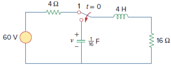
Figure 8.105
For Prob. 8.59.
Expert Solution & Answer
Want to see the full answer?
Check out a sample textbook solution
Students have asked these similar questions
TRUE or FALSE
a. A discontinuous change in the voltage requires an infinite current thus a capacitor resists an abrupt change in the voltage across it.
b. The inductor takes power from the circuit when storing energy and delivers power to the circuit when returning previously stored energy.
The voltage with the following waveform is applied across a 5.00 micro Farad capacitor, what is the amount of total energy stored in the capacitor in the first 6 ms?.
PLease help me .
The figure below shows a simple RC circuit with a 3.10-μF capacitor, a 3.60-MQ resistor, a 9.00-V emf, and a switch. What are the following exactly 8.50 s after the switch is closed?
(a) the charge on the capacitor
μC
(b) the current in the resistor
μA
R
(c) the rate at which the capacitor is storing energy
μW
(d) the rate at which the battery is delivering energy
μW
Chapter 8 Solutions
Fundamentals of Electric Circuits
Ch. 8.2 - The switch in Fig. 8.4 was open for a long time...Ch. 8.2 - For the circuit in Fig. 8.7, find: (a) iL(0+),...Ch. 8.3 - If R = 10 , L = 5 H, and C = 2 mF in Fig. 8.8,...Ch. 8.3 - The circuit in Fig. 8.12 has reached steady state...Ch. 8.4 - In Fig. 8.13, let R = 2 , L = 0.4 H, C = 25 mF,...Ch. 8.4 - Refer to the circuit in Fig. 8.17. Find v(t) for t...Ch. 8.5 - Having been in position a for a long time, the...Ch. 8.6 - Find i(t) and v(t) for t 0 in the circuit of Fig....Ch. 8.7 - Determine v and i for t 0 in the circuit of Fig....Ch. 8.7 - For t 0, obtain v0(t) in the circuit of Fig....
Ch. 8.8 - In the op amp circuit shown in Fig. 8.34, vs =...Ch. 8.9 - Find i(t) using PSpice for 0 t 4 s if the pulse...Ch. 8.9 - Refer to the circuit in Fig. 8.21 (see Practice...Ch. 8.10 - Draw the dual circuit of the one in Fig. 8.46.Ch. 8.10 - For the circuit in Fig. 8.50, obtain the dual...Ch. 8.11 - In Fig. 8.52, find the capacitor voltage vC for t ...Ch. 8.11 - The output of a D/A converter is shown in Fig....Ch. 8 - For the circuit in Fig. 8.58, the capacitor...Ch. 8 - For Review Questions 8.1 and 8.2. 8.2For the...Ch. 8 - When a step input is applied to a second-order...Ch. 8 - If the roots of the characteristic equation of an...Ch. 8 - In a series RLC circuit, setting R = 0 will...Ch. 8 - Prob. 6RQCh. 8 - Refer to the series RLC circuit in Fig. 8.59. What...Ch. 8 - Consider the parallel RLC circuit in Fig. 8.60....Ch. 8 - Match the circuits in Fig. 8.61 with the following...Ch. 8 - Prob. 10RQCh. 8 - For the circuit in Fig. 8.62, find: (a)i(0+) and...Ch. 8 - Using Fig. 8.63, design a problem to help other...Ch. 8 - Refer to the circuit shown in Fig. 8.64....Ch. 8 - In the circuit of Fig. 8.65, find: (a) v(0+) and...Ch. 8 - Refer to the circuit in Fig. 8.66. Determine: (a)...Ch. 8 - In the circuit of Fig. 8.67, find: (a) vR(0+) and...Ch. 8 - A series RLC circuit has R = 20 k, L = 0.2 mH, and...Ch. 8 - Design a problem to help other students better...Ch. 8 - The current in an RLC circuit is described by...Ch. 8 - The differential equation that describes the...Ch. 8 - Prob. 11PCh. 8 - If R = 50 , L = 1.5 H, what value of C will make...Ch. 8 - For the circuit in Fig. 8.68, calculate the value...Ch. 8 - The switch in Fig. 8.69 moves from position A to...Ch. 8 - The responses of a series RLC circuit are...Ch. 8 - Find i(t) for t 0 in the circuit of Fig. 8.70....Ch. 8 - In the circuit of Fig. 8.71, the switch...Ch. 8 - Find the voltage across the capacitor as a...Ch. 8 - Obtain v(t) for t 0 in the circuit of Fig. 8.73....Ch. 8 - The switch in the circuit of Fig. 8.74 has been...Ch. 8 - Calculate v(t) for t 0 in the circuit of Fig....Ch. 8 - Assuming R = 2 k, design a parallel RLC circuit...Ch. 8 - For the network in Fig. 8.76, what value of C is...Ch. 8 - The switch in Fig. 8.77 moves from position A to...Ch. 8 - Using Fig. 8.78, design a problem to help other...Ch. 8 - The step response of an RLC circuit is given by...Ch. 8 - Prob. 27PCh. 8 - A series RLC circuit is described by...Ch. 8 - Solve the following differential equations subject...Ch. 8 - Prob. 30PCh. 8 - Consider the circuit in Fig. 8.79. Find vL(0+) and...Ch. 8 - For the circuit in Fig. 8.80, find v(t) for t 0.Ch. 8 - Find v(t) for t 0 in the circuit of Fig. 8.81.Ch. 8 - Calculate i(t) for t 0 in the circuit of Fig....Ch. 8 - Using Fig. 8.83, design a problem to help other...Ch. 8 - Obtain v(t) and i(t) for t 0 in the circuit of...Ch. 8 - For the network in Fig. 8.85, solve for i(t) for t...Ch. 8 - Refer to the circuit in Fig. 8.86. Calculate i(t)...Ch. 8 - Determine v(t) for t 0 in the circuit of Fig....Ch. 8 - The switch in the circuit of Fig. 8.88 is moved...Ch. 8 - For the network in Fig. 8.89, find i(t) for t 0....Ch. 8 - Given the network in Fig. 8.90, find v(t) for t ...Ch. 8 - The switch in Fig. 8.91 is opened at t = 0 after...Ch. 8 - A series RLC circuit has the following parameters:...Ch. 8 - In the circuit of Fig. 8.92, find v(t) and i(t)...Ch. 8 - Prob. 46PCh. 8 - Find the output voltage vo(t) in the circuit of...Ch. 8 - Given the circuit in Fig. 8.95, find i(t) and v(t)...Ch. 8 - Determine i(t) for t 0 in the circuit of Fig....Ch. 8 - For the circuit in Fig. 8.97, find i(t) for t 0....Ch. 8 - Find v(t) for t 0 in the circuit of Fig. 8.98....Ch. 8 - The step response of a parallel RLC circuit is...Ch. 8 - After being open for a day, the switch in the...Ch. 8 - Using Fig. 8.100, design a problem to help other...Ch. 8 - For the circuit in Fig. 8.101, find v(t) for t 0....Ch. 8 - In the circuit of Fig. 8.102, find i(t) for t 0....Ch. 8 - Given the circuit shown in Fig. 8.103, determine...Ch. 8 - In the circuit of Fig. 8.104, the switch has been...Ch. 8 - The switch in Fig. 8.105 has been in position 1...Ch. 8 - Obtain i1 and i2 for t 0 in the circuit of Fig....Ch. 8 - For the circuit in Prob. 8.5, find i and v for t ...Ch. 8 - Find the response vR(t) for t 0 in the circuit of...Ch. 8 - For the op amp circuit in Fig. 8.108, find the...Ch. 8 - Using Fig. 8.109, design a problem to help other...Ch. 8 - Determine the differential equation for the op amp...Ch. 8 - Obtain the differential equations for vo(t) in the...Ch. 8 - In the op amp circuit of Fig. 8.112, determine...Ch. 8 - For the step function vs = u(t), use PSpice or...Ch. 8 - Given the source-free circuit in Fig. 8.114, use...Ch. 8 - For the circuit in Fig. 8.115, use PSpice or...Ch. 8 - Obtain v(t) for 0 t 4 s in the circuit of Fig....Ch. 8 - The switch in Fig. 8.117 has been in position 1...Ch. 8 - Design a problem, to be solved using PSpice or...Ch. 8 - Draw the dual of the circuit shown in Fig. 8.118.Ch. 8 - Obtain the dual of the circuit in Fig. 8.119.Ch. 8 - Find the dual of the circuii in Fig. 8.120.Ch. 8 - Draw the dual of the circuit in Fig. 8.121.Ch. 8 - An automobile airbag igniter is modeled by the...Ch. 8 - A load is modeled as a 100-mH inductor in parallel...Ch. 8 - A mechanical system is modeled by a series RLC...Ch. 8 - An oscillogram can be adequately modeled by a...Ch. 8 - The circuit in Fig. 8.123 is the electrical analog...Ch. 8 - Figure 8.124 shows a typical tunnel-diode...
Knowledge Booster


Learn more about
Need a deep-dive on the concept behind this application? Look no further. Learn more about this topic, electrical-engineering and related others by exploring similar questions and additional content below.Similar questions
- The switch in the following circuit closes at t-0. If the capacitor is initially discharged, calculate the voltage on the capacitor at t-3s. (R-50KQ, C-33uF) 50 k2 15 V 33 jularrow_forwardFor the circuit at right: a. Immediately after the switch is closed, what is the current in the inductor? 12V b. A long time later, what is the current through the inductor? c. What is the energy stored in the inductor in part (b)? d. A long time later, the switch is opened. Immediately after, what is the voltage across the inductor?arrow_forwardThe figure below shows a simple RC circuit with a 3.50-µF capacitor, a 3.60-MQ resistor, a 9.00-V emf, and a switch. What are the following exactly 6.50 s after the switch is closed? S C R (a) the charge on the capacitor (b) the current in the resistor µA (c) the rate at which the capacitor is storing energy (d) the rate at which the battery is delivering energyarrow_forward
- A series circuit has a capacitor of 0.25 x 10-0 F, a resistor of 5x 10' 2, and an inductor of 1 H. The initial charge on the capacitor is zero. If a 12-volt battery is connected to the ircuit and the circuit is closed at t = 0, determine the charge on the capacitor at t = 0.001 seconds, at t = 0.01 seconds, and at any time t. Also determine the limiting charge as - 0. Enter the exact answer with a < b. The charge at any time is given by the formula Q (1) = (Ae" + Beb + C) x 10-6 coulombs, where %3D x10-6 coulombs as t→ 0 tound your answers to two decimal places. 20 001) = x10-6 Coulomhsarrow_forward1. The image below shows a plot of current versus time in a circuit containing and inductor. Draw a different plot that shows the voltage drop across the inductor as a function of time. It is OK if your plot is not numerically exact, but do show the shape of the time-dependence. I geono erlt gaibnaterob 0.5- 0.2 04 0.6 0.8 1.0 -0.5F Time (s) 1.1. Draw a different plot that shows the voltage drop across the inductor as a function of time. It is OK if plot is not numerically exact, but do show the shape of the time-dependence. your Current (A)arrow_forwardIn the above circuit, the switch is open for a long time.i)The switch closes for 50 us. What is the current through the inductor? Also, what is the voltage at the output with respect to ground just before the switch open?ii) The switch closes. What is the maximum current the inductor will see?arrow_forward
- Given the following image of a practical inductor, what is true? Practical REFF inductor RpC RAC L O Both Rpc and RAC are purposely built into the inductor. Both Rpc and RAC are characteristics of practical inductors, and not actual resistors. ORDC is purposely built into the inductor while RAc is not. O RAC is purposely built into the inductor while Rpc is not.arrow_forwardA capacitor is fully charged in a RC circuit with 16 V of voltage supply to the maximum electric charge of 1.2 x 10⁻³ C. If it took 0.24 s to charge to 2/3 of charge, what will be the maximum current, in the unit of A, when discharging the capacitor? Assume that the same resistor is used for charging and dischargingarrow_forwardFind the inductor current.arrow_forward
- eeeeee t=0 Y. Co) = 15V Ye C4) 0,25MF R In the above circuit, thie switch closes at t= 0. The capacitor is charged to voltage ISV initially. Find the capacitor for the following cases: Ca) R= 8.5k (6) R= 4k () R= 1k * plot the waveforms for each Cuse wwwarrow_forwardPlease show your detailed solution Number 17 A 100-mH inductor is connected across a supply of 50 V AC. For which of the following frequency the circuit will have a current of 0.7958 A? A. 10 kHz C. 10 Hz B. 100 kHz D. 100 Hzarrow_forwardA capacitor C is connected in parallel with a series combination of capacitors of 8 and 4 microF. The voltage drop across capacitor C is 12V. The 3 capacitors have been connected for sometime and have reached their present value. Find the voltage across the capacitor with 8 microF. A. 4V B. 9V C. 3V D. 8Varrow_forward
arrow_back_ios
SEE MORE QUESTIONS
arrow_forward_ios
Recommended textbooks for you
 Introductory Circuit Analysis (13th Edition)Electrical EngineeringISBN:9780133923605Author:Robert L. BoylestadPublisher:PEARSON
 Delmar's Standard Textbook Of ElectricityElectrical EngineeringISBN:9781337900348Author:Stephen L. HermanPublisher:Cengage Learning
 Programmable Logic ControllersElectrical EngineeringISBN:9780073373843Author:Frank D. PetruzellaPublisher:McGraw-Hill Education
 Fundamentals of Electric CircuitsElectrical EngineeringISBN:9780078028229Author:Charles K Alexander, Matthew SadikuPublisher:McGraw-Hill Education
 Electric Circuits. (11th Edition)Electrical EngineeringISBN:9780134746968Author:James W. Nilsson, Susan RiedelPublisher:PEARSON
 Engineering ElectromagneticsElectrical EngineeringISBN:9780078028151Author:Hayt, William H. (william Hart), Jr, BUCK, John A.Publisher:Mcgraw-hill Education,
Introductory Circuit Analysis (13th Edition)
Electrical Engineering
ISBN:9780133923605
Author:Robert L. Boylestad
Publisher:PEARSON
Delmar's Standard Textbook Of Electricity
Electrical Engineering
ISBN:9781337900348
Author:Stephen L. Herman
Publisher:Cengage Learning
Programmable Logic Controllers
Electrical Engineering
ISBN:9780073373843
Author:Frank D. Petruzella
Publisher:McGraw-Hill Education
Fundamentals of Electric Circuits
Electrical Engineering
ISBN:9780078028229
Author:Charles K Alexander, Matthew Sadiku
Publisher:McGraw-Hill Education
Electric Circuits. (11th Edition)
Electrical Engineering
ISBN:9780134746968
Author:James W. Nilsson, Susan Riedel
Publisher:PEARSON
Engineering Electromagnetics
Electrical Engineering
ISBN:9780078028151
Author:Hayt, William H. (william Hart), Jr, BUCK, John A.
Publisher:Mcgraw-hill Education,
ENA 9.2(1)(En)(Alex) Sinusoids & Phasors - Explanation with Example 9.1 ,9.2 & PP 9.2; Author: Electrical Engineering Academy;https://www.youtube.com/watch?v=vX_LLNl-ZpU;License: Standard YouTube License, CC-BY
Electrical Engineering: Ch 10 Alternating Voltages & Phasors (8 of 82) What is a Phasor?; Author: Michel van Biezen;https://www.youtube.com/watch?v=2I1tF3ixNg0;License: Standard Youtube License