
Fundamentals of Electric Circuits
6th Edition
ISBN: 9780078028229
Author: Charles K Alexander, Matthew Sadiku
Publisher: McGraw-Hill Education
expand_more
expand_more
format_list_bulleted
Concept explainers
Videos
Textbook Question
Chapter 8, Problem 18P
Find the voltage across the capacitor as a function of time for t > 0 for the circuit in Fig. 8.72. Assume steady-state conditions exist at t = 0−.
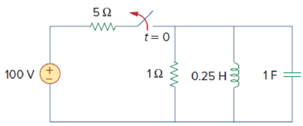
Figure 8.72
For Prob. 8.18.
Expert Solution & Answer
Want to see the full answer?
Check out a sample textbook solution
Students have asked these similar questions
8.15
A 3-pF capacitor charged to 100 V is connected across an uncharged 6-4F capacitor. Find the
voltage and also the initial and final stored energies.
P 8:11
A docs.google.com
36% O
ASIACELL lI.
3. Determine the kind of damping and the value of q for the
arrow refers to number #1 in the figure below
1
0.8
0.6
옷 0.4
0.2
-0.2
6.
8
10
time(s)
A. Overdamping, q equal to zero
B. Underdamping, q equal to zero
C. Critical damping, q equal to zero
D. Overdamping, q more than zero
E. Underdamping, q more than zero
F. Critical damping, q more than zero
G. Overdamping, q less than zero
H. Underdamping, q less than zero
Critical damping, q less than zero
I.
O A
В
D
E
TRUE or FALSE
a. A discontinuous change in the voltage requires an infinite current thus a capacitor resists an abrupt change in the voltage across it.
b. The inductor takes power from the circuit when storing energy and delivers power to the circuit when returning previously stored energy.
Chapter 8 Solutions
Fundamentals of Electric Circuits
Ch. 8.2 - The switch in Fig. 8.4 was open for a long time...Ch. 8.2 - For the circuit in Fig. 8.7, find: (a) iL(0+),...Ch. 8.3 - If R = 10 , L = 5 H, and C = 2 mF in Fig. 8.8,...Ch. 8.3 - The circuit in Fig. 8.12 has reached steady state...Ch. 8.4 - In Fig. 8.13, let R = 2 , L = 0.4 H, C = 25 mF,...Ch. 8.4 - Refer to the circuit in Fig. 8.17. Find v(t) for t...Ch. 8.5 - Having been in position a for a long time, the...Ch. 8.6 - Find i(t) and v(t) for t 0 in the circuit of Fig....Ch. 8.7 - Determine v and i for t 0 in the circuit of Fig....Ch. 8.7 - For t 0, obtain v0(t) in the circuit of Fig....
Ch. 8.8 - In the op amp circuit shown in Fig. 8.34, vs =...Ch. 8.9 - Find i(t) using PSpice for 0 t 4 s if the pulse...Ch. 8.9 - Refer to the circuit in Fig. 8.21 (see Practice...Ch. 8.10 - Draw the dual circuit of the one in Fig. 8.46.Ch. 8.10 - For the circuit in Fig. 8.50, obtain the dual...Ch. 8.11 - In Fig. 8.52, find the capacitor voltage vC for t ...Ch. 8.11 - The output of a D/A converter is shown in Fig....Ch. 8 - For the circuit in Fig. 8.58, the capacitor...Ch. 8 - For Review Questions 8.1 and 8.2. 8.2For the...Ch. 8 - When a step input is applied to a second-order...Ch. 8 - If the roots of the characteristic equation of an...Ch. 8 - In a series RLC circuit, setting R = 0 will...Ch. 8 - Prob. 6RQCh. 8 - Refer to the series RLC circuit in Fig. 8.59. What...Ch. 8 - Consider the parallel RLC circuit in Fig. 8.60....Ch. 8 - Match the circuits in Fig. 8.61 with the following...Ch. 8 - Prob. 10RQCh. 8 - For the circuit in Fig. 8.62, find: (a)i(0+) and...Ch. 8 - Using Fig. 8.63, design a problem to help other...Ch. 8 - Refer to the circuit shown in Fig. 8.64....Ch. 8 - In the circuit of Fig. 8.65, find: (a) v(0+) and...Ch. 8 - Refer to the circuit in Fig. 8.66. Determine: (a)...Ch. 8 - In the circuit of Fig. 8.67, find: (a) vR(0+) and...Ch. 8 - A series RLC circuit has R = 20 k, L = 0.2 mH, and...Ch. 8 - Design a problem to help other students better...Ch. 8 - The current in an RLC circuit is described by...Ch. 8 - The differential equation that describes the...Ch. 8 - Prob. 11PCh. 8 - If R = 50 , L = 1.5 H, what value of C will make...Ch. 8 - For the circuit in Fig. 8.68, calculate the value...Ch. 8 - The switch in Fig. 8.69 moves from position A to...Ch. 8 - The responses of a series RLC circuit are...Ch. 8 - Find i(t) for t 0 in the circuit of Fig. 8.70....Ch. 8 - In the circuit of Fig. 8.71, the switch...Ch. 8 - Find the voltage across the capacitor as a...Ch. 8 - Obtain v(t) for t 0 in the circuit of Fig. 8.73....Ch. 8 - The switch in the circuit of Fig. 8.74 has been...Ch. 8 - Calculate v(t) for t 0 in the circuit of Fig....Ch. 8 - Assuming R = 2 k, design a parallel RLC circuit...Ch. 8 - For the network in Fig. 8.76, what value of C is...Ch. 8 - The switch in Fig. 8.77 moves from position A to...Ch. 8 - Using Fig. 8.78, design a problem to help other...Ch. 8 - The step response of an RLC circuit is given by...Ch. 8 - Prob. 27PCh. 8 - A series RLC circuit is described by...Ch. 8 - Solve the following differential equations subject...Ch. 8 - Prob. 30PCh. 8 - Consider the circuit in Fig. 8.79. Find vL(0+) and...Ch. 8 - For the circuit in Fig. 8.80, find v(t) for t 0.Ch. 8 - Find v(t) for t 0 in the circuit of Fig. 8.81.Ch. 8 - Calculate i(t) for t 0 in the circuit of Fig....Ch. 8 - Using Fig. 8.83, design a problem to help other...Ch. 8 - Obtain v(t) and i(t) for t 0 in the circuit of...Ch. 8 - For the network in Fig. 8.85, solve for i(t) for t...Ch. 8 - Refer to the circuit in Fig. 8.86. Calculate i(t)...Ch. 8 - Determine v(t) for t 0 in the circuit of Fig....Ch. 8 - The switch in the circuit of Fig. 8.88 is moved...Ch. 8 - For the network in Fig. 8.89, find i(t) for t 0....Ch. 8 - Given the network in Fig. 8.90, find v(t) for t ...Ch. 8 - The switch in Fig. 8.91 is opened at t = 0 after...Ch. 8 - A series RLC circuit has the following parameters:...Ch. 8 - In the circuit of Fig. 8.92, find v(t) and i(t)...Ch. 8 - Prob. 46PCh. 8 - Find the output voltage vo(t) in the circuit of...Ch. 8 - Given the circuit in Fig. 8.95, find i(t) and v(t)...Ch. 8 - Determine i(t) for t 0 in the circuit of Fig....Ch. 8 - For the circuit in Fig. 8.97, find i(t) for t 0....Ch. 8 - Find v(t) for t 0 in the circuit of Fig. 8.98....Ch. 8 - The step response of a parallel RLC circuit is...Ch. 8 - After being open for a day, the switch in the...Ch. 8 - Using Fig. 8.100, design a problem to help other...Ch. 8 - For the circuit in Fig. 8.101, find v(t) for t 0....Ch. 8 - In the circuit of Fig. 8.102, find i(t) for t 0....Ch. 8 - Given the circuit shown in Fig. 8.103, determine...Ch. 8 - In the circuit of Fig. 8.104, the switch has been...Ch. 8 - The switch in Fig. 8.105 has been in position 1...Ch. 8 - Obtain i1 and i2 for t 0 in the circuit of Fig....Ch. 8 - For the circuit in Prob. 8.5, find i and v for t ...Ch. 8 - Find the response vR(t) for t 0 in the circuit of...Ch. 8 - For the op amp circuit in Fig. 8.108, find the...Ch. 8 - Using Fig. 8.109, design a problem to help other...Ch. 8 - Determine the differential equation for the op amp...Ch. 8 - Obtain the differential equations for vo(t) in the...Ch. 8 - In the op amp circuit of Fig. 8.112, determine...Ch. 8 - For the step function vs = u(t), use PSpice or...Ch. 8 - Given the source-free circuit in Fig. 8.114, use...Ch. 8 - For the circuit in Fig. 8.115, use PSpice or...Ch. 8 - Obtain v(t) for 0 t 4 s in the circuit of Fig....Ch. 8 - The switch in Fig. 8.117 has been in position 1...Ch. 8 - Design a problem, to be solved using PSpice or...Ch. 8 - Draw the dual of the circuit shown in Fig. 8.118.Ch. 8 - Obtain the dual of the circuit in Fig. 8.119.Ch. 8 - Find the dual of the circuii in Fig. 8.120.Ch. 8 - Draw the dual of the circuit in Fig. 8.121.Ch. 8 - An automobile airbag igniter is modeled by the...Ch. 8 - A load is modeled as a 100-mH inductor in parallel...Ch. 8 - A mechanical system is modeled by a series RLC...Ch. 8 - An oscillogram can be adequately modeled by a...Ch. 8 - The circuit in Fig. 8.123 is the electrical analog...Ch. 8 - Figure 8.124 shows a typical tunnel-diode...
Knowledge Booster


Learn more about
Need a deep-dive on the concept behind this application? Look no further. Learn more about this topic, electrical-engineering and related others by exploring similar questions and additional content below.Similar questions
- Suppose the input to the circuit is a damped ramp of the form Kte−100t V. Find the largest value of K such that the inductor current does not exceed the 40 mA current ratingarrow_forwardA resistor with resistance R and a capacitor with capacitance C are connected in series to an AC voltage source. The time-dependent voltage across the capacitor is given by VC(t) = VC0sin(omegat). What is the amlitude of the total current I(t) in the circuit?arrow_forwardGENERAL RLC CIRCUITS: Solve and show your solution completely. Make sure your answers are in 4 decimals places. A 400 mH coil of negligible resistance is connected to an AC circuit in which an effectivecurrent of 6 mA is flowing. Find out the voltage across the coil if the frequency is 1000 Hz.arrow_forward
- Lesson= Second Order Transient Response A 24-V battery is connected in seires with a 1-Henry (inductor), 8-ohms resistor and a 1/16 Farad ( capacitor) with when the switchis turned “on” at t = 0. And then, what will be the value of the current at t = 0.001 sec.arrow_forwardPlease use Nodal Analysis to solve this problem please. For the following circuit assume it has been in this state for a very long time . Determine the energy stored in the inductor and the capacitor Wl and Wcarrow_forward8. A coil of inductance 9 H and resistance 50 2 in series with a capacitor is supplied at constant voltage from a variable frequency source. If the maximum current of 1 A occurs at 75 Hz, find the frequency when the current is 0.5 Aarrow_forward
- 2. A capacitor having a capacitance of 2.0 µF consists of two metal elec- trodes separated by an insulating spacer made of crystalline silicon. Silicon is a semiconductor, having a conductivity of 1.6x10⁻³ S/m and dielectric constant of 11.7. The capacitor is placed in a series with a 12 volt battery in a closed loop circuit. When steady state is reached, what is the charge on the capacitor, and what is the current in the circuit?arrow_forwardThe voltage applied to a series RLC circuit is v = 200 sin 200t volts and the resulting current is i = 5 sin (200t + 40degree) amp. The capacitor in series has a value of 30 microfarad. Find the inductance of the circuit in Henry.arrow_forward(b) The voltage across a 4 N resistor of an RC circuit in Figure Q8(b) is given by VR (t) = 2e-6tu(t)V. Determine the total energy dissipated by this resistor using Parseval's Theorem. R C Figure Q8(b)arrow_forward
- 1. The capacitor charges toward the source voltage through the resistor. The flash turns on when the capacitor voltage reaches 8 V. If C = 10 μF, find R such that the flash will turn on once per second. 2. Find the differential equation for the current in the circuit shown below.arrow_forwardSince the capacitance specified in the circuit below is limited in the range of 1-10nF, find the capacitance and RL value that will provide the maximum power transfer to the load and calculate the maximum power to be transferred.arrow_forwardFind the steady state current in the RLC circuits when R=18ohm ,L=1H,C=12.5×10^-3F and E = 820 cos 10 t V.assume that initial charge and current are zeroarrow_forward
arrow_back_ios
SEE MORE QUESTIONS
arrow_forward_ios
Recommended textbooks for you
 Introductory Circuit Analysis (13th Edition)Electrical EngineeringISBN:9780133923605Author:Robert L. BoylestadPublisher:PEARSON
 Delmar's Standard Textbook Of ElectricityElectrical EngineeringISBN:9781337900348Author:Stephen L. HermanPublisher:Cengage Learning
 Programmable Logic ControllersElectrical EngineeringISBN:9780073373843Author:Frank D. PetruzellaPublisher:McGraw-Hill Education
 Fundamentals of Electric CircuitsElectrical EngineeringISBN:9780078028229Author:Charles K Alexander, Matthew SadikuPublisher:McGraw-Hill Education
 Electric Circuits. (11th Edition)Electrical EngineeringISBN:9780134746968Author:James W. Nilsson, Susan RiedelPublisher:PEARSON
 Engineering ElectromagneticsElectrical EngineeringISBN:9780078028151Author:Hayt, William H. (william Hart), Jr, BUCK, John A.Publisher:Mcgraw-hill Education,
Introductory Circuit Analysis (13th Edition)
Electrical Engineering
ISBN:9780133923605
Author:Robert L. Boylestad
Publisher:PEARSON
Delmar's Standard Textbook Of Electricity
Electrical Engineering
ISBN:9781337900348
Author:Stephen L. Herman
Publisher:Cengage Learning
Programmable Logic Controllers
Electrical Engineering
ISBN:9780073373843
Author:Frank D. Petruzella
Publisher:McGraw-Hill Education
Fundamentals of Electric Circuits
Electrical Engineering
ISBN:9780078028229
Author:Charles K Alexander, Matthew Sadiku
Publisher:McGraw-Hill Education
Electric Circuits. (11th Edition)
Electrical Engineering
ISBN:9780134746968
Author:James W. Nilsson, Susan Riedel
Publisher:PEARSON
Engineering Electromagnetics
Electrical Engineering
ISBN:9780078028151
Author:Hayt, William H. (william Hart), Jr, BUCK, John A.
Publisher:Mcgraw-hill Education,
ENA 9.2(1)(En)(Alex) Sinusoids & Phasors - Explanation with Example 9.1 ,9.2 & PP 9.2; Author: Electrical Engineering Academy;https://www.youtube.com/watch?v=vX_LLNl-ZpU;License: Standard YouTube License, CC-BY
Electrical Engineering: Ch 10 Alternating Voltages & Phasors (8 of 82) What is a Phasor?; Author: Michel van Biezen;https://www.youtube.com/watch?v=2I1tF3ixNg0;License: Standard Youtube License