
Electronics Fundamentals: Circuits, Devices & Applications
8th Edition
ISBN: 9780135072950
Author: Thomas L. Floyd, David Buchla
Publisher: Prentice Hall
expand_more
expand_more
format_list_bulleted
Concept explainers
Videos
Textbook Question
Chapter 8, Problem 50P
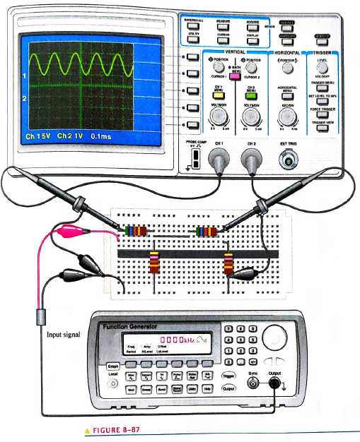
Based on the instrument settings and an examination of the scope display and the circuit board in Figure 8-87 determine the frequcncy and peak value of the input signal and output signal. The waveform shown is channel. Draw the channel 2 waveform as it would appear on the scope with the indicated scttings.
Expert Solution & Answer
Want to see the full answer?
Check out a sample textbook solution
Students have asked these similar questions
Draw a voltage multiplier(6 times) with half wave voltage doubler and discuss it generally..
2. Draw and explain the difference between clipper circuit and clamper circuit output
waveform
Part A- Why negative peaks are eliminated in Half Wave Rectification and how this can be achieved in
Full Wave Rectification without eliminating these peaks?
Chapter 8 Solutions
Electronics Fundamentals: Circuits, Devices & Applications
Ch. 8 - The period of a 60 Hz sine wave is 16.7 ms.Ch. 8 - The rms and average value of a sine wave are the...Ch. 8 - Prob. 3TFQCh. 8 - The peak value of a sine wave is the same as its...Ch. 8 - The number of radians in 360 is 2 .Ch. 8 - In a three-phase electrical system, the phases are...Ch. 8 - The purpose of an exciter is to supply dc rotor...Ch. 8 - In an automotive alternator, the output current is...Ch. 8 - Prob. 9TFQCh. 8 - A synchronous motor can be used when constant...
Ch. 8 - Prob. 1STCh. 8 - During each cycle, a sine wave reaches a peak...Ch. 8 - A sine wave with a frequency of 12 kHz is changing...Ch. 8 - Prob. 4STCh. 8 - When a sine wave has a frequency of 60 Hz, in 10 s...Ch. 8 - Prob. 6STCh. 8 - Prob. 7STCh. 8 - The average value of a 10 V peak sine wave over...Ch. 8 - Prob. 9STCh. 8 - Prob. 10STCh. 8 - The instantaneous value of a 15 A peak sine wave...Ch. 8 - If the rms curren through a 10k resistor is 5 m A,...Ch. 8 - Prob. 13STCh. 8 - Prob. 14STCh. 8 - Prob. 15STCh. 8 - Prob. 16STCh. 8 - Prob. 17STCh. 8 - Prob. 1TSCCh. 8 - Prob. 2TSCCh. 8 - Prob. 3TSCCh. 8 - Prob. 4TSCCh. 8 - Prob. 5TSCCh. 8 - Calculate the frequency for each of the following...Ch. 8 - Calculate the period for each of the following...Ch. 8 - A sine wave goes through 5 cycles in 10s. What is...Ch. 8 - A sine wave has a frequency of 50 kHz. How many...Ch. 8 - How long does it take a 10 kHz sine wave to...Ch. 8 - A sine wave has a peak value of 12 V. Determine...Ch. 8 - A sinusoidal current has an rms value of 5 mA....Ch. 8 - For the sine wave in Figure 8-74, determine the...Ch. 8 - If each horizontal division in Figure 8-74 is 1...Ch. 8 - In Figure 8-74, what is the instantaneous voltage...Ch. 8 - Sine wave A has a positive-going zero crossing at...Ch. 8 - One sine wave has a positive peak at 75 and...Ch. 8 - Draw two since waves as follows: Sline wave A is...Ch. 8 - Convert the following angular values from degrees...Ch. 8 - Convert the following angular values from radians...Ch. 8 - A certain sine wave has a positive-going zero...Ch. 8 - For a particular 0 reference sinusoidal current,...Ch. 8 - For a 0 reference sinw wave with an rms value of...Ch. 8 - Sine wave A lags sine wave B by 30. Both have peak...Ch. 8 - Repeat Problem 19 for the case when sine wave A...Ch. 8 - A sinusoidal voltage is applied to the resistive...Ch. 8 - Find the half-cycle average values of the voltages...Ch. 8 - Determine th rms voltage across R3 in Figure 8-77.Ch. 8 - A sine wave with an rms value of 10.6 V is riding...Ch. 8 - How much dc voltage must be added to a 3 V rms...Ch. 8 - A 6 V peak sine wave is riding on a dc voltage of...Ch. 8 - The conductive wire loop on the rotor of a simple...Ch. 8 - Prob. 28PCh. 8 - At what speed of rotation must a four-pole...Ch. 8 - A common frequency for alternators on aircraft is...Ch. 8 - Prob. 31PCh. 8 - Explain how the field in a three-phase motor...Ch. 8 - From the graph in Figure 8-78, determine the...Ch. 8 - Determine the duty cycle for each pulse waveform...Ch. 8 - Find the average value of each positive-going...Ch. 8 - What is the frequency of each waveform in Figure...Ch. 8 - What is the frequency of each sawtooth waveform in...Ch. 8 - A square wave has a period of 40s. List the first...Ch. 8 - What is the fundamental frequency of the square...Ch. 8 - Determine the peak value and the period of the...Ch. 8 - Determine the rms value and the frequency of the...Ch. 8 - Determine the rms value and the frequency of the...Ch. 8 - Find the amplitude, pulse width, and duty cycle...Ch. 8 - A certain sine wave has a frequency of 2.2 kHz and...Ch. 8 - Figure 8-84 shows a sinusoidal voltage source in...Ch. 8 - A nonsinusoidal waveform called a stairstep is...Ch. 8 - Refer to the oscilloscope screen in Figure 8-86....Ch. 8 - Accurately draw on a grid representing the scope...Ch. 8 - Accurately draw on a grid representing the scope...Ch. 8 - Based on the instrument settings and an...Ch. 8 - Examine the circuit board and the oscilloscope...Ch. 8 - Prob. 52PCh. 8 - www. prenhall.com/floyd. 53. Open file P08-53 and...Ch. 8 - www. prenhall.com/floyd. 54. Open file P08-54 and...Ch. 8 - www. prenhall.com/floyd. 55. Open file P08-55 and...Ch. 8 - www. prenhall.com/floyd. 56. Open file P08-56 and...
Knowledge Booster


Learn more about
Need a deep-dive on the concept behind this application? Look no further. Learn more about this topic, electrical-engineering and related others by exploring similar questions and additional content below.Similar questions
- what is peak voltage?arrow_forwardin a given figure, a signal is shown on a CRO screen. The CRO voltage per division (Volt/Div.) knob is set on 5 V, and Time per Division (Time/Div) knob is set on 10 ms. Calculate the signal amplitude and frequency. THEICN Ground LEVE NTENS TRO NP FOCUS VO ON INVERT NVERT CHI 40arrow_forwardDetermine the output voltage waveform. Indicate the peak values (up to 2 significant decimal places) during the positive and negative half cycles. No need to indicate the sign.arrow_forward
- The waveform displayed on an oscilloscope is as shown in Figure The 'time/cm' switch is set to 0.2 ms/cm, and the 'volts/cm' switch is set to 40 V/cm. Determine the (i) amplitude of waveform Q, (ii) peak to peak value of waveform P, (iii) frequency of waveform Parrow_forwardDetermine the output voltage waveform of the circuit. Indicate the positive peak and negative peak.arrow_forwardClippers and Clampers. Determine the output waveform for each circuit. Show your solutions.arrow_forward
- C2 (i). Draw the Schematic diagram and explain the working of LVDT and write any two applications of it. C2 (ii). A sinusoidal waveform is displayed on a C.R.O. screen, the time/cm switch is on 40 µs/cm and the volt/cm switch is on 20 V/cm. The width of one complete cycle is 3 cm and the peak to peak distance is 5.6 cm. Determine the following: The frequency is The magnitude of the sine voltage is The amplitude is The R.M.S voltage isarrow_forwardA sinusoidal voltage wave form of peak voltage í V and frequency f = 60Hz is applied to a bridge rectifier and to half wave rectifier separately. The Differences of average values and output frequencies arearrow_forwardThe waveform on the screen of horizontal division an oscilloscope is 4 squares high from bottom to top, as in the Figure below. sensitivity is Volts/Div, what is the peak- to-peak bottom) of the input signal, and what is the amplitude of vertical division If the 2.5 horizontal divisions set to 0.2 voltage (top-to- 4 vertical divisions the oscillation?arrow_forward
- İL ic io, la IS Vo, Va vs vL vC LOAD SWITCH vD iD G Redraw the circuit when the switch is ON and OFF. II. Draw the wave shape of is(source current), isw (switch current), vsw (switch voltage), i, (inductor current), v, (inductor voltage), ic(capacitor current), vc(capacitor voltage),ip(diode current), vp(diode voltage). I. TAKE APPROPRIATE POLARITY OF THE VOLTAGES. MARK THE POLARITY IN YOUR FIGURE. TAKE APPROPRIATE DIRECTIONS OF THE CURRENTS. MARK THE DIRECTIONS IN YOUR FIGURE.arrow_forwardWhat is extrinsic semiconductorarrow_forwardThe waveform displayed on an oscilloscope is as shown in Figure The 'time/cm' switch is set to 0.5 ms/cm, and the 'volts/cm' switch is set to 0.2 V/cm. Determine the (i) amplitude of waveform Q, (ii) peak to peak value of waveform P, (iii) frequency of waveform P and (iv) phase angle difference between P and Q in Degrees. Upload your Answers steps in the "Final Answer Submission" Link provided in the Moodle. (i) Amplitude of waveform Q = (ii) Peak to peak value of waveform P = (iii) Frequency of waveform P =arrow_forward
arrow_back_ios
SEE MORE QUESTIONS
arrow_forward_ios
Recommended textbooks for you
 Introductory Circuit Analysis (13th Edition)Electrical EngineeringISBN:9780133923605Author:Robert L. BoylestadPublisher:PEARSON
 Delmar's Standard Textbook Of ElectricityElectrical EngineeringISBN:9781337900348Author:Stephen L. HermanPublisher:Cengage Learning
 Programmable Logic ControllersElectrical EngineeringISBN:9780073373843Author:Frank D. PetruzellaPublisher:McGraw-Hill Education
 Fundamentals of Electric CircuitsElectrical EngineeringISBN:9780078028229Author:Charles K Alexander, Matthew SadikuPublisher:McGraw-Hill Education
 Electric Circuits. (11th Edition)Electrical EngineeringISBN:9780134746968Author:James W. Nilsson, Susan RiedelPublisher:PEARSON
 Engineering ElectromagneticsElectrical EngineeringISBN:9780078028151Author:Hayt, William H. (william Hart), Jr, BUCK, John A.Publisher:Mcgraw-hill Education,
Introductory Circuit Analysis (13th Edition)
Electrical Engineering
ISBN:9780133923605
Author:Robert L. Boylestad
Publisher:PEARSON
Delmar's Standard Textbook Of Electricity
Electrical Engineering
ISBN:9781337900348
Author:Stephen L. Herman
Publisher:Cengage Learning
Programmable Logic Controllers
Electrical Engineering
ISBN:9780073373843
Author:Frank D. Petruzella
Publisher:McGraw-Hill Education
Fundamentals of Electric Circuits
Electrical Engineering
ISBN:9780078028229
Author:Charles K Alexander, Matthew Sadiku
Publisher:McGraw-Hill Education
Electric Circuits. (11th Edition)
Electrical Engineering
ISBN:9780134746968
Author:James W. Nilsson, Susan Riedel
Publisher:PEARSON
Engineering Electromagnetics
Electrical Engineering
ISBN:9780078028151
Author:Hayt, William H. (william Hart), Jr, BUCK, John A.
Publisher:Mcgraw-hill Education,
Number Systems Introduction - Decimal, Binary, Octal & Hexadecimal; Author: The Organic Chemistry Tutor;https://www.youtube.com/watch?v=FFDMzbrEXaE;License: Standard Youtube License