
Electronics Fundamentals: Circuits, Devices & Applications
8th Edition
ISBN: 9780135072950
Author: Thomas L. Floyd, David Buchla
Publisher: Prentice Hall
expand_more
expand_more
format_list_bulleted
Concept explainers
Videos
Textbook Question
Chapter 8, Problem 45P
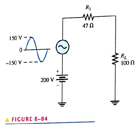
Figure 8-84 shows a sinusoidal voltage source in series with a dc source. Effectively, the two voltages are superimposed. Draw the total voltage across
Expert Solution & Answer
Want to see the full answer?
Check out a sample textbook solution
Students have asked these similar questions
8PFE-5 What is the current I, in the circuit ?
6ej2t
+1
-j1Q
Io
Please show your detailed solution
Number 14
The current in a series inductive circuit is 7.5 A at 25 Hz. The circuit takes 425 W, and the power factor is 0.47. The resistance of the circuit is
A. 7.32 ohms C. 7.98 ohms
B. 7.86 ohms D. 7.56 ohms
4. A sinusoidal voltage has an r.m.s. value of 240 V. What is the peak value of the voltage?
Chapter 8 Solutions
Electronics Fundamentals: Circuits, Devices & Applications
Ch. 8 - The period of a 60 Hz sine wave is 16.7 ms.Ch. 8 - The rms and average value of a sine wave are the...Ch. 8 - Prob. 3TFQCh. 8 - The peak value of a sine wave is the same as its...Ch. 8 - The number of radians in 360 is 2 .Ch. 8 - In a three-phase electrical system, the phases are...Ch. 8 - The purpose of an exciter is to supply dc rotor...Ch. 8 - In an automotive alternator, the output current is...Ch. 8 - Prob. 9TFQCh. 8 - A synchronous motor can be used when constant...
Ch. 8 - Prob. 1STCh. 8 - During each cycle, a sine wave reaches a peak...Ch. 8 - A sine wave with a frequency of 12 kHz is changing...Ch. 8 - Prob. 4STCh. 8 - When a sine wave has a frequency of 60 Hz, in 10 s...Ch. 8 - Prob. 6STCh. 8 - Prob. 7STCh. 8 - The average value of a 10 V peak sine wave over...Ch. 8 - Prob. 9STCh. 8 - Prob. 10STCh. 8 - The instantaneous value of a 15 A peak sine wave...Ch. 8 - If the rms curren through a 10k resistor is 5 m A,...Ch. 8 - Prob. 13STCh. 8 - Prob. 14STCh. 8 - Prob. 15STCh. 8 - Prob. 16STCh. 8 - Prob. 17STCh. 8 - Prob. 1TSCCh. 8 - Prob. 2TSCCh. 8 - Prob. 3TSCCh. 8 - Prob. 4TSCCh. 8 - Prob. 5TSCCh. 8 - Calculate the frequency for each of the following...Ch. 8 - Calculate the period for each of the following...Ch. 8 - A sine wave goes through 5 cycles in 10s. What is...Ch. 8 - A sine wave has a frequency of 50 kHz. How many...Ch. 8 - How long does it take a 10 kHz sine wave to...Ch. 8 - A sine wave has a peak value of 12 V. Determine...Ch. 8 - A sinusoidal current has an rms value of 5 mA....Ch. 8 - For the sine wave in Figure 8-74, determine the...Ch. 8 - If each horizontal division in Figure 8-74 is 1...Ch. 8 - In Figure 8-74, what is the instantaneous voltage...Ch. 8 - Sine wave A has a positive-going zero crossing at...Ch. 8 - One sine wave has a positive peak at 75 and...Ch. 8 - Draw two since waves as follows: Sline wave A is...Ch. 8 - Convert the following angular values from degrees...Ch. 8 - Convert the following angular values from radians...Ch. 8 - A certain sine wave has a positive-going zero...Ch. 8 - For a particular 0 reference sinusoidal current,...Ch. 8 - For a 0 reference sinw wave with an rms value of...Ch. 8 - Sine wave A lags sine wave B by 30. Both have peak...Ch. 8 - Repeat Problem 19 for the case when sine wave A...Ch. 8 - A sinusoidal voltage is applied to the resistive...Ch. 8 - Find the half-cycle average values of the voltages...Ch. 8 - Determine th rms voltage across R3 in Figure 8-77.Ch. 8 - A sine wave with an rms value of 10.6 V is riding...Ch. 8 - How much dc voltage must be added to a 3 V rms...Ch. 8 - A 6 V peak sine wave is riding on a dc voltage of...Ch. 8 - The conductive wire loop on the rotor of a simple...Ch. 8 - Prob. 28PCh. 8 - At what speed of rotation must a four-pole...Ch. 8 - A common frequency for alternators on aircraft is...Ch. 8 - Prob. 31PCh. 8 - Explain how the field in a three-phase motor...Ch. 8 - From the graph in Figure 8-78, determine the...Ch. 8 - Determine the duty cycle for each pulse waveform...Ch. 8 - Find the average value of each positive-going...Ch. 8 - What is the frequency of each waveform in Figure...Ch. 8 - What is the frequency of each sawtooth waveform in...Ch. 8 - A square wave has a period of 40s. List the first...Ch. 8 - What is the fundamental frequency of the square...Ch. 8 - Determine the peak value and the period of the...Ch. 8 - Determine the rms value and the frequency of the...Ch. 8 - Determine the rms value and the frequency of the...Ch. 8 - Find the amplitude, pulse width, and duty cycle...Ch. 8 - A certain sine wave has a frequency of 2.2 kHz and...Ch. 8 - Figure 8-84 shows a sinusoidal voltage source in...Ch. 8 - A nonsinusoidal waveform called a stairstep is...Ch. 8 - Refer to the oscilloscope screen in Figure 8-86....Ch. 8 - Accurately draw on a grid representing the scope...Ch. 8 - Accurately draw on a grid representing the scope...Ch. 8 - Based on the instrument settings and an...Ch. 8 - Examine the circuit board and the oscilloscope...Ch. 8 - Prob. 52PCh. 8 - www. prenhall.com/floyd. 53. Open file P08-53 and...Ch. 8 - www. prenhall.com/floyd. 54. Open file P08-54 and...Ch. 8 - www. prenhall.com/floyd. 55. Open file P08-55 and...Ch. 8 - www. prenhall.com/floyd. 56. Open file P08-56 and...
Knowledge Booster


Learn more about
Need a deep-dive on the concept behind this application? Look no further. Learn more about this topic, electrical-engineering and related others by exploring similar questions and additional content below.Similar questions
- 60. Design a circuit to limit a 20 V rms sinusoidal voltage to a maximum positive amplitude of 10 V and a maximum negative amplitude of -5 V using a single 14 V de voltage source. 61 Datermine the volto in the girRuit F Figura 1 1?arrow_forwardA non-sinusoidal current source (iT=2+1.5sin1000t+ 1cos3000t-0.5sin4000t) A is applied to the circuit shown. Find the total power? * 42 iL ww iT ic c -J92 J42 O 55 W 20 W 39 W O 28 Warrow_forwardThe maximum value of sinusoidal voltage is given by Vm= 1 V, What is the value of Peak to Peak voltage?arrow_forward
- The frequency of the sinusoidal voltage source in the circuit in (Figure 1) is adjusted until the current io is in phase with vgarrow_forwardDraw roughly the arc characteristics in alternating currents with a frequency of 50 Hz and 500 Hz, explain brieflyarrow_forwardValue of series impedance if inductance is 4mH , resistance is 40 ohm and frequency is 50 Hz.arrow_forward
- 1. The phasor diagram representing four alternating currents is shown in the figure below where the length of each phasor represents the amplitude of that waveform. Write down the standard expression for each waveform. L-4A 1₁-7A 70⁰ 50⁰ -1₂-6 1₂=5Aarrow_forwardThe source in the circuit shown is a sinusoidal source. The supply voltages across various elements are marked in the figure. The input voltage is: 3V- ww -14 V-10V moon Itarrow_forwardA non-sinusoidal current source (iT=2+1.5sin10o0t+ 1cos3000t-0.5sin4000t) A is applied to the circuit shown. Find the total power? * İL iT ic -J9Ω J4Q O 55 W 20 W 39 W 28 Warrow_forward
- The current in a circuit known to consist only of resistance and inductance in series is 8.31Amps when the circuit is connected across 120V 25 hz. When connected across 120V 60 hz mains, the current is 5.3Amps. Determine the resistance and inductance.arrow_forward1) Two identical voltage waveforms of difference phase angles are shown in Figure B. Write down the expression of waveforms A and B clearly. HUS Voltage (V) 8 0 K/N B 7: ST otarrow_forwardThe complex volt amperes in a series circuit are (4300- j2500) and the current is (25 + j43.3)A.Find the applied voltage.arrow_forward
arrow_back_ios
SEE MORE QUESTIONS
arrow_forward_ios
Recommended textbooks for you
 Power System Analysis and Design (MindTap Course ...Electrical EngineeringISBN:9781305632134Author:J. Duncan Glover, Thomas Overbye, Mulukutla S. SarmaPublisher:Cengage Learning
 Electricity for Refrigeration, Heating, and Air C...Mechanical EngineeringISBN:9781337399128Author:Russell E. SmithPublisher:Cengage Learning
 Delmar's Standard Textbook Of ElectricityElectrical EngineeringISBN:9781337900348Author:Stephen L. HermanPublisher:Cengage Learning
Power System Analysis and Design (MindTap Course ...
Electrical Engineering
ISBN:9781305632134
Author:J. Duncan Glover, Thomas Overbye, Mulukutla S. Sarma
Publisher:Cengage Learning
Electricity for Refrigeration, Heating, and Air C...
Mechanical Engineering
ISBN:9781337399128
Author:Russell E. Smith
Publisher:Cengage Learning
Delmar's Standard Textbook Of Electricity
Electrical Engineering
ISBN:9781337900348
Author:Stephen L. Herman
Publisher:Cengage Learning
NMOS vs PMOS and Enhancement vs Depletion Mode MOSFETs | Intermediate Electronics; Author: CircuitBread;https://www.youtube.com/watch?v=kY-ka0PriaE;License: Standard Youtube License