
Concept explainers
Videos
For the state of stress shown, determine two values of σy for which the maximum shearing stress is 10 ksi.
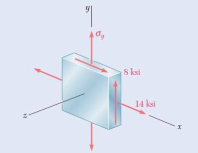
Fig. P7.77
The two values of
Answer to Problem 77P
The values of
Explanation of Solution
Given information:
The components of stress
The maximum shear stress
Calculation:
Consider
Modify Equation (1) as shown below.
Calculate the average normal stress
Substitute
Calculate the value u as shown below.
Substitute
Case 1:
For
Calculate the value of
Substitute
Calculate the average normal stress
Substitute
Calculate the principal stresses
Substitute
Hence, the principal stresses are
Calculate the maximum shearing stress as shown below.
Substitute
For
Calculate the value of
Substitute
Calculate the average normal stress
Substitute
Calculate the principal stresses
Substitute
Hence, the principal stresses are
Calculate the maximum shearing stress as shown below.
Substitute
Hence, the value of
Case 2:
Assume the minimum principal stress
Calculate the maximum principal stress as shown below.
Substitute
The maximum principal stress
Substitute
Substitute
Calculate the value of
Substitute
Calculate the value of R as shown below.
Substitute
Calculate the average normal stress
Substitute
Calculate the principal stress
Substitute
Hence, the principal stresses
Therefore, the value of
Want to see more full solutions like this?
Chapter 7 Solutions
EBK MECHANICS OF MATERIALS


- 7. Knowing that 0=40° and P=9 kN, determine (a) the smallest allowable diameter of the pin at Bif the average shearing stress in the pin is not exceed 120 MPa, (b) the corresponding average bearing stress in the member AB at B, (c) the corresponding average bearing stress in each of the support brackets at B. P 16 mm 750 mm 750 mm 50 mm- 12 inmarrow_forwardProblem 4 The steel pipe AB has a 102-mam outer diameter and a 6-mm wall thickness. Knowing that arm CD is rigidly attached to the pipe, determine the principal stresses and the maximum shearing stress at point K. And then show stress on Mohr's circle. 200 mm 6 mm B H D 51 mm 150 mm xarrow_forward19. knowing that a force P of magnitude 75 N is applied to the pedestal shown, determine (a) the diameter of the pin at C for which the average shearing stress in the pin is 40 MPa, (b) the corresponding bearing stress in the pedestal at C, (c) the corresponding bearing stress in each support bracket at C. 75 mm 9 mm - 300 mm- B 125 mm D 5 mmarrow_forward
- PROBLEM 7.26 0.2 m The axle of an automobile is acted upon by the forces and couple shown. Knowing that the diameter of the solid axle is 32 mm, determine (a) the principal planes and principal stresses at point H located on top of the axle, (b) the maximum shearing stress at the same point. 3 kN 350 N- m 3 kN Omax = 18.67 MPa = -158,5 MPa O minarrow_forward1.4 kN - m PROBLEM 8.43 A 10-kN force and a 1.4-kN - m couple are applied at the top of the 65-mm diameter brass post shown. Determine the principal stresses and maximum shearing stress at (a) point H, (b) point K. 10 kN 240 mm Omax = 30.0 MPa O min =-30.0 MPa Tmax = 30.0 MPa Omax = 7.02 MPa Omin =-96.0 MPa Tmay =51.5 MPaarrow_forward7.58 For the state of stress shown, determine the range of values of 0 for which the normal stress o, is equal to or less than 100 MPa. 90 MPa Try 60 MPa the Fig. P7.58 and P7.59arrow_forward
- .29 Two wooden members of uniform rectangular cross section are joined by the simple glued scarf splice shown. Knowing that P= 11 kN, determine the normal and shearing stresses in the glued splice. 150 mm 15 75 mm Fig. P1.29 and P1.30arrow_forward5. A load of 7,000 N acts on the machine part shown in Fig. 5a. The machine part has a uniform thickness of 15 mm (i.e., 15-mm thickness in the z direction). Determine the normal and shear stresses acting at points H and K, which are shown in detail in Fig. 5b. For eachpoint, show these stresses on a stress element. Fig. 5a Fig. 5b 2.5 in. 400 mm 5.2kN-m 20 KN 7.5KN 2.0 inarrow_forwardProblem 2. Three loads are applied to the short rectangular post shown In Fig. 2(a). The cross- sectional dimensions of the post are shown in Fig. 2(b). Determine: Me (a) The normal and shear stresses and points H and K; (b) The principal stresses and maximum in-plane shear stress at point H, and show the orientation of theses stresses in an appropriate sketch. No. M2 y 50 mm 210 kN %3D 120 mm (Naー 75 mm K 65 kN 30 mm 95 kN 160 mm 150 mm 30 mm Y-axis is the w to the sectin paimt Hond E امقره Fig. 2(b) 文 Section Proputics A= 120 X160=19200 mm Lx=160 - 40960000 mm-4094r L= 160x128 5KNス50 m-) %3D %3D = 23040000mm'= 23; 40Xlʻmm7 Int Faicesarrow_forward
- A steel pipe of 400-mm outer diameter is fabricated from 10-mm-thick plate by welding along a helix that forms an angle of 20°with a plane perpendicular to the axis of the pipe. Knowing that the maximum allowable normal and shearing stresses in the directions respectively normal and tangential to the weld are σ = 60 MPa and τ = 36 MPa, determine the magnitude P of the largest axial force that can be applied to the pipe.arrow_forwardTwo gage marks are placed exactly 250 mm apart on a 12-mm-diameter aluminum rod with E = 73 GPa and an ultimate strength of 140 MPa. Knowing that the distance between the gage marks is 250.28 mm after a load is applied, determine the stress in the rodarrow_forwardA spherical gas container made of steel has a 20-ft outer diameter and a wall thickness of 7/16 in. Knowing that the internal pressure is 75 psi, determine the maximum normal stress and the maximum shearing stress in the container.arrow_forward
 Elements Of ElectromagneticsMechanical EngineeringISBN:9780190698614Author:Sadiku, Matthew N. O.Publisher:Oxford University Press
 Mechanics of Materials (10th Edition)Mechanical EngineeringISBN:9780134319650Author:Russell C. HibbelerPublisher:PEARSON
 Thermodynamics: An Engineering ApproachMechanical EngineeringISBN:9781259822674Author:Yunus A. Cengel Dr., Michael A. BolesPublisher:McGraw-Hill Education
 Control Systems EngineeringMechanical EngineeringISBN:9781118170519Author:Norman S. NisePublisher:WILEY
 Mechanics of Materials (MindTap Course List)Mechanical EngineeringISBN:9781337093347Author:Barry J. Goodno, James M. GerePublisher:Cengage Learning
 Engineering Mechanics: StaticsMechanical EngineeringISBN:9781118807330Author:James L. Meriam, L. G. Kraige, J. N. BoltonPublisher:WILEY