
Concept explainers
Videos
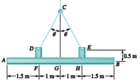
For the structural member of Prob. 7.53, determine (a) the angle θ for which the maximum absolute value of the bending moment in beam AB is as small as possible, (b) the corresponding value of |M|max. (Hint: Draw the bending-moment diagram and then equate the absolute values of the largest positive and negative bending moments obtained.)
PROBLEM 7.53 Two small channel sections DF and EH have been welded to the uniform beam AB of weight W = 3 kN to form the rigid structural member shown. This member is being lifted by two cables attached at D and E. Knowing that θ = 30° and neglecting the weight of the channel sections, (a) draw the shear and bending-moment diagrams for beam AB, (b) determine the maximum absolute values of the shear and bending moment in the beam.
Want to see the full answer?
Check out a sample textbook solution
Chapter 7 Solutions
VECTOR MECHANICS FOR ENGINEERS: STATICS


- (B) Q: The cantilever beam shown below has a circular cross section of 50mm outer diameter. Portion AB of the beam is hollow, with an inner diameter of 35mm. If the allowable bending stress is 140 MPa, determine (1) the largest allowable uniformly distributed load (w) that can be applied to the beam; (2) the bending stress at a point that is 7 mm below the top of the beam at section D. 50 mm W D B O! 35 mm A - 750 mm 250 mmarrow_forward4. A (250 mm) depth and (150mm) width rectangular beam is subjected to maximum bending moment of (750 KN.m), Determine: a. The maximum stress in the beam ? b. If the value of Young Modulus (E) for the beam material is (200 GPa), find the radius of curvature for that portion of the beam where the bending is maximum ? c. The value of the longitudinal stress at a distance of (65mm) from the top surface of the beam ?arrow_forwardThe rigid bar DEF is welded at point D to the steel beam AB. For the loading shown, determine (a) the equations defining the shear and bending at portion AD of the steel beam AB, (b) the location and magnitude of the largest bending moment. (Hint: Replace the 700 N load applied at F by an equivalent force-couple system at D) 750 N/m B D 000 E 2.4 m X 0.9 m 700 N -1.5 m.arrow_forward
- 5.7 For the cantilever beam shown in the figure, find (a) the maximum bending stress and its location; and (b) the bending stress at a point 20 mm from the top of the beam on section B. 1.0 kN/m 150 mm C A 2 m- 50 mm 6 m FIG. PS.7arrow_forward27. The cantilever beam shown carries a concentrated load, P = 500 N, and a uniformly distributed load, w = 200 N/m. Determine the moment, in N-m, at a section 1.25 m to the left of the free end. Use a = b = 500 mm, and c = 1 m. a. b. 150 175 a (13 P C. d. b 200 225 W сarrow_forward(b) The gudgeon pin is used to connect the piston and the connecting rod. Show from first principles that the maximum bending moment acting on the gudgeon pin is given by: PL M = 8 where P is the maximum gas load and L is the length of the pinarrow_forward
- Problem a. Sketch a Free Body Diagram for the section of the beam left of a cutting plane located a distance x from A, where 4.0 marrow_forwardProblem 7. The 30-mm diameter shaft is subjected to the vertical and horizontal loadings of two pulleys as shown. It is supported on two journal bearings at A and B which offer no resistance to axial loading. Furthermore, the coupling to the motor at C can be assumed not to offer any support to the shaft. The shaft is subjected to both Mz and My internal bending moment components. (a) Draw a bending moment diagram for each component. (b) Since all axes through the circle's center for circular shaft are principal axis, then the resultant M = √M²+ M² can be used to determine the y maximum bending stress. Determine the location and magnitude of maximum normal stress due to bending developed in the shaft. X 150 N 1 m 2 150 N 1 m E 60 mm 1 m 100 mm 1 m 400 N 400 Narrow_forward(13) A beam is to be rectangular in section with depth twice the width. The distance between supports is 6 feet and there are two concentrated downward loads : 6,000 lb 18 in. from the left support, and 5,000 lb., 40 in. from the left support. (a) Draw shear and bending-moment diagrams. (b) Using steel with E equal to 30,000,000 psi and ultimate strength of 75,000 psi, determine the beam dimensions if the maximum stress is to be 15,000 psi. (c) Using cast iron with E equal to 10,000,000 psi and ultimate strength of 30,000 psi, determine the beam dimensions if the maximum stress is 5,000 psi.arrow_forwardIn order to reduce the bending moment in the cantilever beam AB , a cable and counterweight are permanently attached at end B . Determine the magnitude of the counterweight for which the maximum absolute value of the bending moment in the beam is as small as possible and the corresponding value of |M| max. Consider (a) the case when the distributed load is permanently applied to the beam, (b) the more general case when the distributed load may either be applied or removed.arrow_forward7.9 Draw the shearing-force and bending-moment diagrams for the following beams: A cantilever of length 20 m carrying a load of 10 kN at a distance of 15 m from the supported end. A cantilever of length 20 m carrying a load of 10 kN uniformly distributed over the inner 15 m of its length A cantilever of length 12 m carrying a load of 8 kN, applied 5 m from the supported end, and a load of 2kNlm over its whole length A beam, 20 m span, simply-supported at each end and carrying a vertical load of 20 kN at a distance 5 m from one support. A beam, 16 m span, simply-supported at each end and carrying a vertical load of 2.5 kN at a distance of 4 m from one support and the beam itself weighing 500 N per metre.arrow_forwardA cable AB of span L and a simple beam A'B' of the same span are subjected to identical vertical loadings as shown. Show that the magnitude of the bending moment at a point C' in the beam is equal to the product T0h, where T0 is the magnitude of the horizontal component of the tension force in the cable and h is the vertical distance between point C and the chord joining the points of support A and B.arrow_forwardarrow_back_iosSEE MORE QUESTIONSarrow_forward_ios
 Elements Of ElectromagneticsMechanical EngineeringISBN:9780190698614Author:Sadiku, Matthew N. O.Publisher:Oxford University Press
 Mechanics of Materials (10th Edition)Mechanical EngineeringISBN:9780134319650Author:Russell C. HibbelerPublisher:PEARSON
 Thermodynamics: An Engineering ApproachMechanical EngineeringISBN:9781259822674Author:Yunus A. Cengel Dr., Michael A. BolesPublisher:McGraw-Hill Education
 Control Systems EngineeringMechanical EngineeringISBN:9781118170519Author:Norman S. NisePublisher:WILEY
 Mechanics of Materials (MindTap Course List)Mechanical EngineeringISBN:9781337093347Author:Barry J. Goodno, James M. GerePublisher:Cengage Learning
 Engineering Mechanics: StaticsMechanical EngineeringISBN:9781118807330Author:James L. Meriam, L. G. Kraige, J. N. BoltonPublisher:WILEY