
Principles of Foundation Engineering (MindTap Course List)
8th Edition
ISBN: 9781305081550
Author: Braja M. Das
Publisher: Cengage Learning
expand_more
expand_more
format_list_bulleted
Concept explainers
Videos
Textbook Question
thumb_up100%
Chapter 7, Problem 7.2P
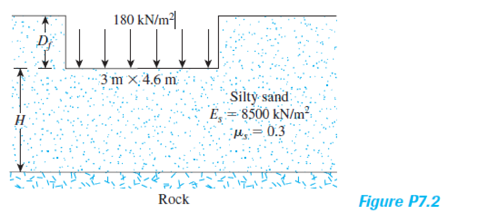
A planned flexible load area (see Figure P7.2) is to be 3 m × 4.6 m and carries a uniformly distributed load of 180 kN/m2. Estimate the elastic settlement below the center of the loaded area. Assume that Df = 2 m and H = ∞. Use Eq. (7.4).
Expert Solution & Answer

Trending nowThis is a popular solution!

Students have asked these similar questions
A simply supported beam 4 m long has a cross section shown. Determine the
maximum uniformly distributed load which can be applied over the entire length of
the beam if the shearing stress is limited to 1.5 MPa. Answer must be in kN/m.
Given: b = 130 mm and d = 180 mm.
%3D
280 mm
b
170 mm
A simply supported beam 4 m long has a cross section shown. Determine the
maximum uniformly distributed load which can be applied over the entire length of
the beam if the shearing stress is limited to 1.6 MPa. Answer must be in kN/m.
Given: b = 130 mm and d = 170 mm.
%3D
250 mm
180 mm
A planned flexible load area (see Figure P7.2) is to be 3 m x 4.6 m and carries a uniformly distributed load of 180 kN/m2. Estimate the elastic settlement below the center of the loaded area. Assume that Df = 2 m and H = ∞ . Use Eqn 7.4
Chapter 7 Solutions
Principles of Foundation Engineering (MindTap Course List)
Ch. 7 - Prob. 7.1PCh. 7 - A planned flexible load area (see Figure P7.2) is...Ch. 7 - Prob. 7.3PCh. 7 - Prob. 7.4PCh. 7 - Prob. 7.5PCh. 7 - Prob. 7.6PCh. 7 - Prob. 7.7PCh. 7 - Prob. 7.8PCh. 7 - Solve Problem 7.8 using Eq. (7.29). Ignore the...Ch. 7 - A continuous foundation on a deposit of sand layer...
Knowledge Booster


Learn more about
Need a deep-dive on the concept behind this application? Look no further. Learn more about this topic, civil-engineering and related others by exploring similar questions and additional content below.Similar questions
- A circular Beam with roller joint R L y y oo = 298.6055 Pa Ro = 2.0649 m L = 61 m Material Data E[ GPA] Oyp [MPa] p [kg/m^3 V 200 0.3 700 7800 Find: Displacement in X, Y, Z direction, von misses stress, tresca stress, and triaxial stress at x = L, at x = L/2 and x = 0. Please show all workarrow_forward4- A strip load of q= 100 lb/ft is applied over a width, B=10 ft. Determine the increase in vertical stress at point A located z =4.6 ft below the surface. Given: x-8.2 ft. q = load per unit arcaarrow_forwardA simply supported beam 4 m long has a cross section shown. Determine the maximum uniformly distributed load which can be applied over the entire length of the beam if the shearing stress is limited to 1.3 MPa. Answer must be in kN/m. Given: b = 120 mm and d = 180 mm.arrow_forward
- 4. A beam of rectangular cross section 40 mm by 100 mm is carrying a bending moment of M = 21 kN.m about its strong axis. Determine the residual stresses following removal of the bending moment (show the residual stress distribution). Consider oy = 240 MPa, and E = 200 GPa. Solution: 100 mm 40 mmarrow_forward3. A beam cross section is shown to the right. A vertical shear force, vertical shear force, V = 150 kN is applied to the beam. Determine the shear stress at point b, and at point a. Ans: 2 = 79.8 MPa, t = 101.6 MPa 6 mm 80 mm 40 mm 6 mm 12 12 mm mm 80 mm b.arrow_forward1. A tubular beam with circular cross section has an outer diameter do = 300 mm and wall thickness t = 10 mm as shown. The beam is subjected to a vertical shear force V=200 kN at this section. The shear stress formula is T=VQ/(It). (a) Determine the maximum shear stress and its location. (b) Check whether the stress resultant equals the vertical shear force. Hint: Firstly determine the location of zero shear stress. Z do = 300 mm 1 =10mmarrow_forward
- Q.3.A tapering conical bar of 1 m length has diameter of 20 mm and 50 mm at the two ends. Find the elongation of the bar under an axial tensile load of 250kN. Take E= 250 GPa. Answer:arrow_forwardA solid circular shaft of diameter d is subjected to a torque T. the maximum normal stress induced in the shaft is O a. 32T/nd^3 O b. Zero O c. 8T/nd^3 O d. 16T/Ttd^3arrow_forwardA propped cantilever beam of length ? = 1 m, with an inner hinge at point B, carries a uniformly distributed load ?, as shown in Figure Q1 (a). The beam is made from a circular hollow section with an inner radius of ?? = 5 cm and a thickness of ? = 2 cm (refer to Figure Q1 (b)). The maximum allowable longitudinal stress of the beam is 150 N/mm2.arrow_forward
- A torque T = 780 kN.m is applied to a hollow shaft shown that has a uniform 8-mm wall thickness. Neglecting the effect of stress concentrations, determine the shearing stress at points a and b. 90 mm a 60° b The shearing stress at point a is The shearing stress at point b is GPa. GPa.arrow_forwardThe vertical stress increment (Ao) due to a point load acting on the surface of linearly elastic medium is given as: g = 4 n = 17 3P23 27vr? +2 where P is the magnitude of the load, r is the lateral distance, and z is the depth of the point where the stress is to be calculated. If P = 10g kN andr = 1.5 m, determine (by using two methods: fixed-point and Newton-Raphson method) the depth z at which the stress increment Ao= 10n kN/m2. (Take g=student group number A-1, B=2, C=3, D=4, and E=5, n=student number in his/her group, and ɛ =1x10⁻⁶)arrow_forwardTwo identical loads distributed over circular areas are applied on an elastic two-layer system, as shown in the figure below. D E = 150,000 psi v = 0.5 h E = 30,000 psi v = 0.5 D/2 the dimensions and the magnitude of the surface stresses are: r= 6.5 in D= 16.25 in g = 75 psi h = 6.5 in Determine: 1. The total vertical deflection at point A 2. The total vertical deflection at point B 3. The total vertical deflection at point Carrow_forward
arrow_back_ios
SEE MORE QUESTIONS
arrow_forward_ios
Recommended textbooks for you

 Structural Analysis (10th Edition)Civil EngineeringISBN:9780134610672Author:Russell C. HibbelerPublisher:PEARSON
 Principles of Foundation Engineering (MindTap Cou...Civil EngineeringISBN:9781337705028Author:Braja M. Das, Nagaratnam SivakuganPublisher:Cengage Learning
 Fundamentals of Structural AnalysisCivil EngineeringISBN:9780073398006Author:Kenneth M. Leet Emeritus, Chia-Ming Uang, Joel LanningPublisher:McGraw-Hill Education
 Traffic and Highway EngineeringCivil EngineeringISBN:9781305156241Author:Garber, Nicholas J.Publisher:Cengage Learning
Structural Analysis (10th Edition)
Civil Engineering
ISBN:9780134610672
Author:Russell C. Hibbeler
Publisher:PEARSON
Principles of Foundation Engineering (MindTap Cou...
Civil Engineering
ISBN:9781337705028
Author:Braja M. Das, Nagaratnam Sivakugan
Publisher:Cengage Learning
Fundamentals of Structural Analysis
Civil Engineering
ISBN:9780073398006
Author:Kenneth M. Leet Emeritus, Chia-Ming Uang, Joel Lanning
Publisher:McGraw-Hill Education
Traffic and Highway Engineering
Civil Engineering
ISBN:9781305156241
Author:Garber, Nicholas J.
Publisher:Cengage Learning
Stress Distribution in Soils GATE 2019 Civil | Boussinesq, Westergaard Theory; Author: Gradeup- GATE, ESE, PSUs Exam Preparation;https://www.youtube.com/watch?v=6e7yIx2VxI0;License: Standard YouTube License, CC-BY