
Videos
The beam AB is pin supported at A and supported by a cable BC. A separate cable CG is used to hold up the frame. If AB weighs 120 lb/ft and the column FC has a weight of 180 lb/ft, determine the resultant internal loadings acting on cross sections located at points D and E. Neglect the thickness of both the beam and column in the calculation.
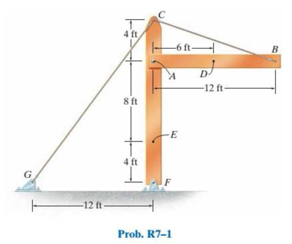
Find the resultant internal loadings acting on cross sections located at D and E.
Answer to Problem 1RP
The resultant internal loadings at cross section at D are
The resultant internal loadings at cross section at E are
Explanation of Solution
Given information:
The beam AB is pin supported at A and supported by a cable BC.
The weight of the beam AB is
The weight of the column FC is
Calculation:
Find the loading at the center of the beam AB
Substitute
Convert the unit from lb to kip.
Sketch the Free Body Diagram of the beam AB shown in Figure 1.
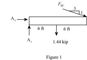
Refer to Figure 1.
Find the angle of cable BC to the horizontal
Find the tension in cable BC as shown below.
Take moment about A is Equal to zero.
Find the support reaction at A as shown below.
Apply the Equations of Equilibrium as shown below.
Summation of forces along horizontal direction is Equal to zero.
Summation of forces along vertical direction is Equal to zero.
Find the loading at the center of the beam AD
Substitute
Convert the unit from lb to kip.
Sketch the Free Body Diagram of the section for point D as shown in Figure 2.
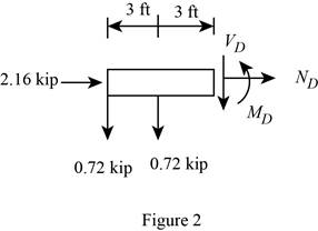
Refer to Figure 2.
Find the internal loadings as shown below.
Apply the Equations of Equilibrium as shown below.
Summation of forces along horizontal direction is Equal to zero.
Summation of forces along vertical direction is Equal to zero.
Take moment about D is Equal to zero.
Hence, the resultant internal loadings at cross section at D are
Find the loading at the center of the column FC
Substitute
Convert the unit from lb to kip.
Sketch the Free Body Diagram of the beam FC shown in Figure 3.
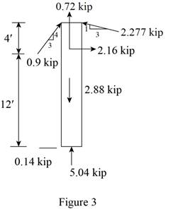
Refer to Figure 3.
Find the angle of cable CG to the horizontal.
Find the tension in cable CG as shown below.
Summation of forces along horizontal direction is Equal to zero.
Find the loading at the center of the column FE
Substitute
Convert the unit from lb to kip.
Sketch the Free Body Diagram of the section for point E as shown in Figure 4.
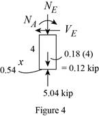
Refer to Figure 4.
Find the internal loadings as shown below.
Apply the Equations of Equilibrium as shown below.
Summation of forces along horizontal direction is Equal to zero.
Summation of forces along vertical direction is Equal to zero.
Take moment about E is Equal to zero.
Therefore, the resultant internal loadings at cross section at E are
Want to see more full solutions like this?
Chapter 7 Solutions
Statics and Mechanics of Materials (5th Edition)
Additional Engineering Textbook Solutions
Manufacturing Engineering & Technology
Foundations of Materials Science and Engineering
HEAT+MASS TRANSFER:FUND.+APPL.
Engineering Mechanics: Dynamics (14th Edition)
DeGarmo's Materials and Processes in Manufacturing
Shigley's Mechanical Engineering Design (McGraw-Hill Series in Mechanical Engineering)


- The cable of the suspension bridge spans L=140m with a sag H=20m. The cable supports a uniformly distributed load of w0 N/m along the horizontal. If the maximum allowable force in the cable is 4 MN, determine the largest permissible value of w0.arrow_forwardHorizontal plates are connected to the bar AB whose length varies linearly from zero to HA, as shown. The total weight of the set of plates is W. Determine: The maximum shear stress in member AB and the torsional rotation at point B. The diameter of member AB is equal to d and its shear modulus is G.arrow_forwardThe triangular block below is subjected to the Loads P=1200 lb and 400 lb. If AB=8 in, and BC is 6in., resolve each load into components normal and tangential to AC.arrow_forward
- Determine the resultant internal loadings at cross-sections at points E and F on the assembly.arrow_forwardDetermine the resultant internal loadings acting on the cross-section at point C in the beam. The load D has a mass of 300 kg and is being hoisted by the motor M with constant velocity.arrow_forwardThe metal stud punch is subjected to a force of 120 N on the handle. determine the magnitude of the reactive force at the pin A and in the short link BC. Also, determine the resultant internal loadings acting on the cross section at point D.arrow_forward
- The brace and drill bit is used to drill a hole at O. If the drill bit jams when the brace is subjected to the forces shown determine the resultant internal loadings acting on the cross-section of the drill bit at A.arrow_forwardDetermine the combined loadings and draw them on a volume element: (a)Section A-A, Point A on the cross section (b)Section B-B, Point B on the cross sectionarrow_forwardThe beam supports the triangular distributed load shown. Determine the resultant internal loadings on the cross section at point C. Assume the reactions at the supports A and B are vertical.arrow_forward
- The beam is supporting a distributed load of w=660 lb/ft. Determine the magnitudes of the resultant internal loadings acting on section b–b through the centroid C on the beam. Show all work and any FBDs that apply.arrow_forwardThe shaft is supported by a smooth thrust bearing at A and a smooth journal bearing at B. Determine the resultant internal loadings acting on the cross-section at C.arrow_forward1–1. The shaft is supported by a smooth thrust bearing at B and a journal bearing at C. Determine the resultant internal loadings acting on the cross section at E. Problem 1–1arrow_forward
 International Edition---engineering Mechanics: St...Mechanical EngineeringISBN:9781305501607Author:Andrew Pytel And Jaan KiusalaasPublisher:CENGAGE L