
Concept explainers
Calculate the horizontal deflection and vertical deflection at joint B.
Answer to Problem 1P
The horizontal deflection at joint B is
The vertical deflection at joint B is
Explanation of Solution
Given information:
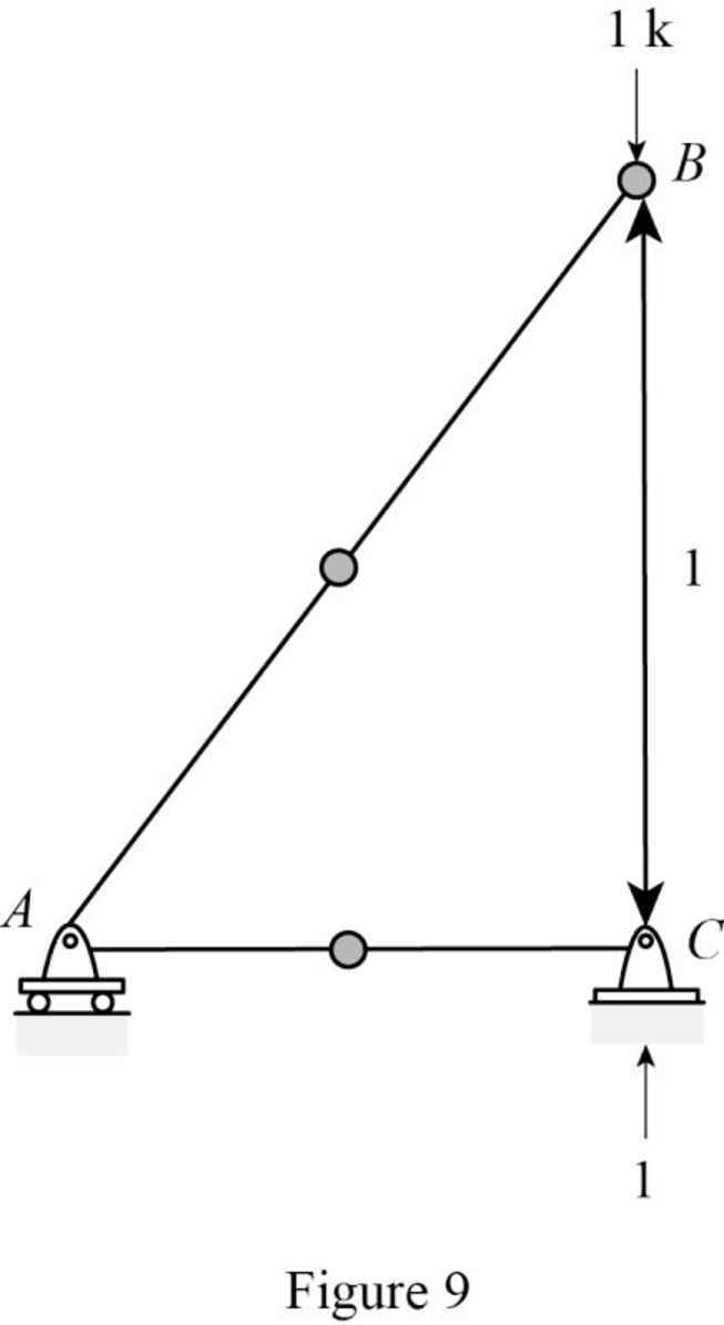
The truss is given in the Figure.
The value of E is 29,000 ksi and the value of A is
Procedure to find the deflection of truss by virtual work method is shown below.
- For Real system: If the deflection of truss is determined by the external loads, then apply method of joints or method of sections to find the real axial forces (F) in all the members of the truss.
- For virtual system: Remove all given real loads, apply a unit load at the joint where is deflection is required and also in the direction of desired deflection. Use method of joints or method of sections to find the virtual axial forces
- Finally use the desired deflection equation.
Apply the sign conventions for calculating reactions, forces and moments using the three equations of equilibrium as shown below.
- For summation of forces along x-direction is equal to zero
- For summation of forces along y-direction is equal to zero
- For summation of moment about a point is equal to zero
Method of joints:
The negative value of force in any member indicates compression (C) and the positive value of force in any member indicates Tension (T).
Condition for zero force member:
- 1. If only two non-collinear members are connected to a joint that has no external loads or reactions applied to it, then the force in both the members is zero.
- 2. If three members, two of which are collinear are connected to a joint that has no external loads or reactions applied to it, then the force in non-collinear member is zero.
Calculation:
Consider the real system.
Find the member axial force (F) for the real system using method of joints:
Let
Let
Sketch the free body diagram of the truss as shown in Figure 1.
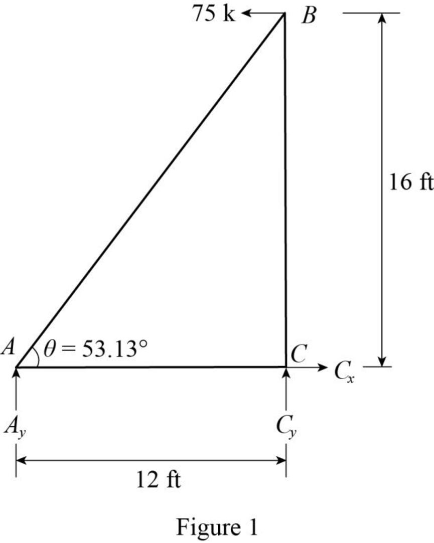
Find the reactions at the supports using equilibrium equations:
Summation of forces along x-direction is equal to 0.
Summation of moments about C is equal to 0.
Summation of forces along y-direction is equal to 0.
Substitute
Sketch the free body diagram of joint A as shown in Figure 2.
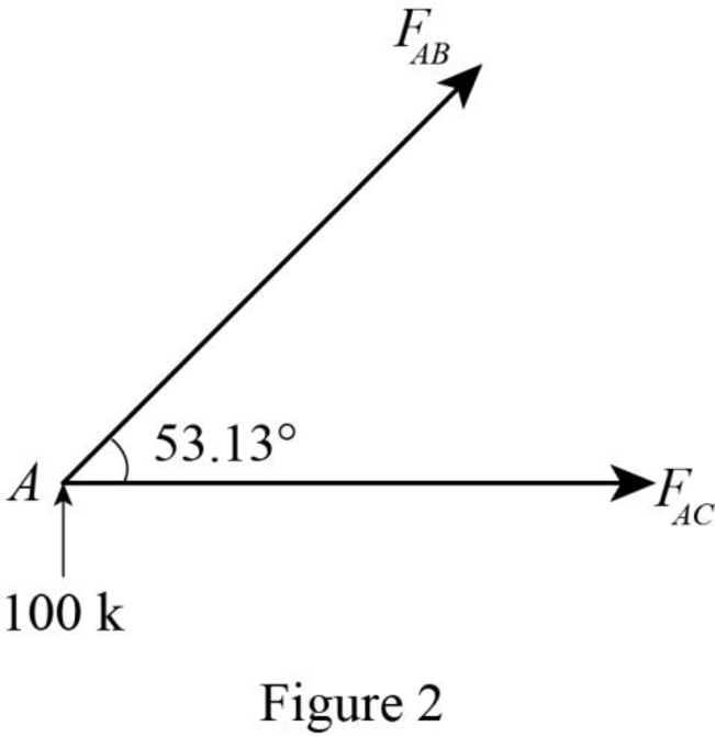
Apply equilibrium equation to the free body diagram of joint A:
Summation of forces along y-direction is equal to 0.
Summation of forces along x-direction is equal to 0.
Substitute
Sketch the free body diagram of joint C as shown in Figure 3.
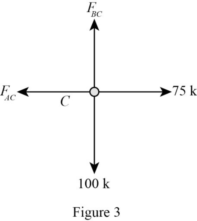
Apply equilibrium equation to the free body diagram of joint C:
Summation of forces along y-direction is equal to 0.
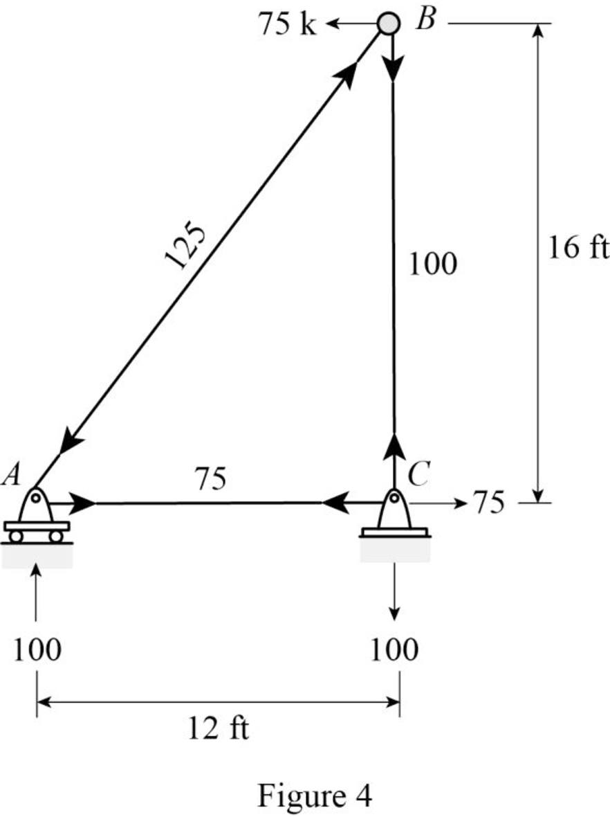
Sketch the resultant diagram of the real forces as shown in Figure 4.
Consider the virtual system:
For horizontal deflection apply l k at joint B in horizontal direction.
Find the member axial force (
Sketch the free body diagram of the truss as shown in Figure 5.
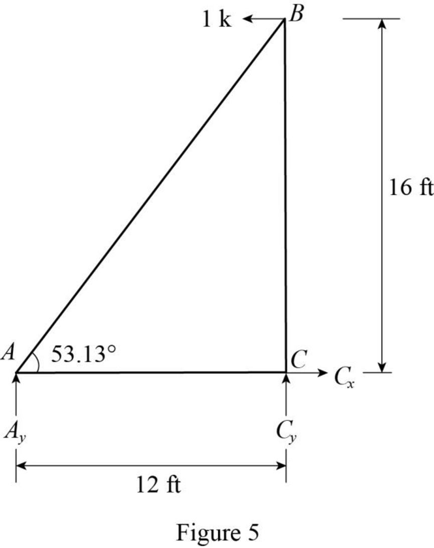
Refer Figure 1 and Figure 5.
The real system is similar to the virtual system except the load of 75k acting in the horizontal direction. So divide the real force (F) by 75 to obtain the virtual force
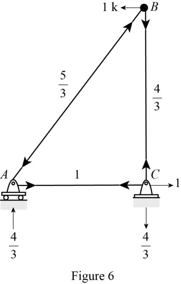
The virtual force in the member AB is
Substitute
The virtual force in the member AC is
Substitute
The virtual force in the member BC is
Substitute
Sketch the resultant diagram of the virtual system
Consider the virtual system:
For vertical deflection apply l k at joint B in vertical direction.
Find the member axial force
Sketch the free body diagram of the truss as shown in Figure 7.
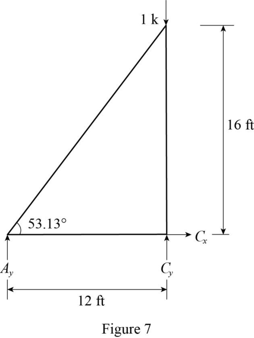
Find the reactions at the supports using equilibrium equations:
Summation of forces along x-direction is equal to 0.
Summation of moments about C is equal to 0.
Summation of forces along y-direction is equal to 0.
Substitute
The reaction at A is zero. So the member AB and AC satisfies the zero force member condition.
Therefore,
Sketch the free body diagram of joint C as shown in Figure 8.
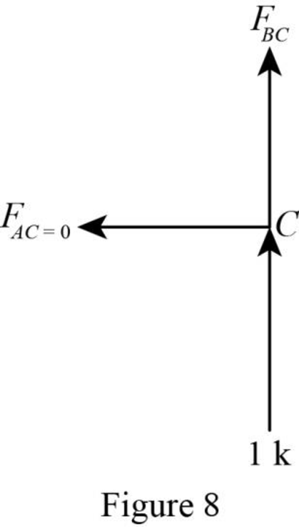
Apply equilibrium equation to the free body diagram of joint C:
Summation of forces along y-direction is equal to 0.
Sketch the resultant diagram of the virtual system
The expression to find the deflection
Here, L is the length of the member, A is the area of the member, and E is the young’s modulus of the member.
For E and A is constant, the expression becomes,
Length of the member AC is,
Similarly convert the length of the remaining member and show in column 2 of Table 1.
Find the product of
Substitute 1 k for
Similarly calculate for the remaining member and show in column 5 of Table 1.
Find the product of
Substitute 0 for
Similarly calculate for the remaining member and show in column 7 of Table 1.
Frame a table for the above calculated values.
Summarize the calculated values as shown in Table 1.
| Member |
L | |||||
| AC | 144 | 75 | 1 | 10,800 | 0 | 0 |
| AB | 240 | 50,000 | 0 | 0 | ||
| BC | 192 | 100 | 25,600 | |||
| 86,400 |
Find the horizontal deflection at joint B
Substitute
Therefore, the horizontal deflection at joint B is
Find the vertical deflection at joint B
Substitute
Therefore, the vertical deflection at joint B is
Want to see more full solutions like this?
Chapter 7 Solutions
Structural Analysis


- Only 100% sure experts solve it correct complete solutions ok fastarrow_forwardIf a contractor has to quit a project due to a lack of funds what would be the best way to handle the breach of contract?arrow_forwardTo determine the elevation of a point such as B in Fig. 24 in the text, the following procedure was used: With the transit set up over a point such as A whose elevation is 128.3 ft, the height of the transverse axis above A was 4.84 ft and the vertical angle b between the horizontal line CD through the transverse axis and the line of sight to the point B was +12º 42'. Then a point such as E was marked on the ground on the line between A and B and at a horizontal distance from A equal to 50.00 ft. Finally, with the transit set up over the point E, the difference in elevation between the point A and the transverse axis F of the transit at E was found to be 3.47 ft, and the vertical angle d between the horizontal line through F and the line of sight to the point B was +18º 07'. The elevation of the point B isarrow_forward
- Which of the following statements is not true when considering precision in surveying?A. Measuring angles to the nearest minute and distances to the nearest hundredth of a foot is usually sufficient for locating theroute of a highway.B. A very accurate survey provides a very high degree of precision.C. Precision is defined as the degree of correctness applied in instruments.D. The most precise instruments can produce inaccurate results i f subjected to mechanical or human error.arrow_forwardWhich of the following is not desirable when marking a transit point for conducting a survey?A. Embedding a nail into soft concreteB. Driving a tack flush with the top o f a wooden hubC. Chiseling a cross on an embedded rockD. Driving a nail with flagging into undisturbed eartharrow_forwardA one-story building as shown in the plan, if the height of the concrete floor is 320 m, the width of the wall is 0.24 and the roof is made of reinforced concrete, the amount of iron for the roof is 100 kg m3 and there are downward depressions with a depth of 0.40 and a width of 0.25 along the wall and the amount of reinforcing iron is 89 kg m3 and there are 14 columns with dimensions of 0.500.30 and a height of 2.80, the amount of reinforcing iron is 120 kg m3 Find The amount of bricks used for construction The amount of mortar used for construction (cement + sand) -1 -2 The amount of plaster for the building from the inside is 2 cm thick (cement + sand) -3 Quantity of floor tiles for the room Quantity of concrete for the ceiling and beams. Ceiling thickness: 0.20 m. Total amount of reinforcing steel for the roof (tons) Quantity of reinforcing steel for columns (tons) Total amount of reinforcing steel for balls (tons) -4 -5 -6 -7 -8arrow_forward
- K Course Code CE181303 Course Title Hours per week L-T-P Credit C Fluid Mechanics 3-1-0 MODULE 1: Fluid Properties: Fluid-definition, types; physical properties of fluid-density, specific weight, specific volume, specific gravity, viscosity- Newton's law of viscosity, surface tension, compressibility of fluids, capillarity. MODULE 2: Fluid Statics: Hydrostatic pressure, pressure height relationship, absolute and gauge pressure, measurement of pressure-manometer, pressure on submerged plane and curved surfaces, centre of pressure; buoyancy, equilibrium of floating bodies, metacentre; fluid mass subjected to accelerations. MODULE 3: Fluid Kinematics: Types of motion- steady and unsteady flow, uniform and no uniform flow, laminar and turbulent flow, and path lines, stream tube, stream function compressible and incompressible flow, one, two & three dimensional flow; stream lines, streak lines and velocity potential, flow net and its drawing: free and forced vortex. MODITE Q. A closed…arrow_forwardH.W: For the tank shown in figure below, Find The amount of salt in the tank at any time. Ans: x = 2(100+t) 1500000 (100 + t)² Qin = 3 L/min Cin = 2 N/L V = 100 L Xo=50N Qout = 2 L/min Cout? 33arrow_forward- Find reactions and draw Shear and Bending Moment Diagram. 30 N 15 N/m D B A 2 m 1 m 2 mmarrow_forward
- : A 5ms- long current pulse is desired for two linear lamps connected in series and pumped at a total energy input of (1KJ). Each of lamps has an arc-length of (10cm) and a bore of (1cm). If we assume a peak current of (i, -650A). Design a multiple mesh network including number of LC sections, inductance and capacitance per section and capacitor voltage. Laser designarrow_forwardWhat would be the best way to handle when a contractor misses a concrete pour deadline which causes delays for other contractors?arrow_forwardPlease solve manuallyarrow_forward